My aim is to check voltages later this morning (Chicago time LOL), when my 1 yr. old naps.
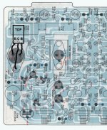
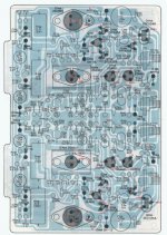
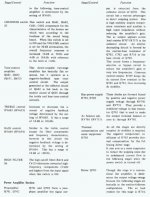
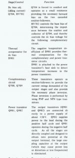
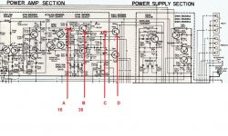
Here's some more pics. One is a full version of the power amp board showing everything. And I hope the 2 pages describing the power amp section come out clear enough to read.
Here's some more pics. One is a full version of the power amp board showing everything. And I hope the 2 pages describing the power amp section come out clear enough to read.
Attachments
I did a test. 20v across B -E. Will double check hopefully soon.
Definitely recheck that. A base emitter junction behaves just like a diode when forwar biased. The volt drop can not exceed approx 0.8v even if the current continues to increase. If it were reversed biased then it usually limits at some indeterminate value but that's a condition that is never normally encountered. It's a no go area. For the NPN device (the MJE) the base will always be positive with respect to the emitter.
Thanks for the layout etc...
My readings are:
E 36.6
C 54.5
B 16.2
How I measure: Black probe connects to chassis ground and red probe does the measuring while unit is powered on. The collector reading seems right; just not "getting" why the other numbers are off so much. Looks like I'll be needing to do more probing to determine the problem.
I checked my pinouts on the new transistor a few times to make sure I didn't goof up there. Aim to do more voltage reading on other components on this board later today. Time to re read the manual lol!
Major setback: Tried to take measurements of Q902 which is on heatsink. As I touched red probe to E, or B don't remember which, I got a spark then my power amp board began to release the magic smoke! No shock or anything; I don't wear jewelry and I never have 2 hands near the chassis LOL!
Sorry to say, that this is just turning into a larger problem the more I mess with it. I'll stick with mono, single ended guitar amp builds I guess. Mooly, thanks for all the help, but with a wife, 2 kids, a huge TO DO list on my home projects, I don't have the time or energy to restore this receiver I bought for 30 bucks on *bay.
Sorry to say, that this is just turning into a larger problem the more I mess with it. I'll stick with mono, single ended guitar amp builds I guess. Mooly, thanks for all the help, but with a wife, 2 kids, a huge TO DO list on my home projects, I don't have the time or energy to restore this receiver I bought for 30 bucks on *bay.
That's a shame...
Those readings indicate that Q 902 was duff. When I jumped at the driver being faulty (the high B-E volts) I never thought to ask over the polarity of that reading... I assumed it was Base at 33 rather than the emitter.
tbh it's probably still a worthwhile and fairly easy fix even after what has happened. Output transistors and probably new 0.5 ohms and perhaps a few other minor components that may have been damaged.
Put it on one side and then you can always come back to it")
Those readings indicate that Q 902 was duff. When I jumped at the driver being faulty (the high B-E volts) I never thought to ask over the polarity of that reading... I assumed it was Base at 33 rather than the emitter.
tbh it's probably still a worthwhile and fairly easy fix even after what has happened. Output transistors and probably new 0.5 ohms and perhaps a few other minor components that may have been damaged.
Put it on one side and then you can always come back to it
Your right . After a good night's sleep, my head's a little clearer and more rational - for the moment. The list for replacement parts in this instance isn't terribly long, so I'll get that going and just take my time. Already found suitable output transistors at Mouser LOL.
. After a good night's sleep, my head's a little clearer and more rational - for the moment. The list for replacement parts in this instance isn't terribly long, so I'll get that going and just take my time. Already found suitable output transistors at Mouser LOL.Just doing a visual inspection the power amp too see where the "magic smoke" came from. Found the culprit right away - resistor R720, a 330 ohm burnt french fry now. After looking it up in the service manual, it appears to be part of the speaker protection circuit.
That's the only obvious burnt component I could find so far. My current to do list is to order this replacement as well as output transistors and some 0.5 5W wirewounds.
We'll see how long my break from this lasts...
That's the only obvious burnt component I could find so far. My current to do list is to order this replacement as well as output transistors and some 0.5 5W wirewounds.
We'll see how long my break from this lasts...
Attachments
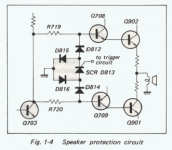
The speaker protection circuit is highly unusual on this amp... that's worth a discussion in its own right.
If R720 is burnt then there are a couple of possible paths that current could have flowed to cause this...
To rebuild this you need a definite plan to follow and a safe way of powering it all up basically consisting of the bulb tester to limit major current flow and damage.
If it were me I would actually remove for now D704, Q705, Q706 and Q707 as these are in the protection circuit. Test them out of circuit but leave them out for now. The amp will work without these.
Did the outputs Q901 and 902 read faulty doing a simple check with a DVM on "diode" test range.
You need to check all the low value resistors in that area, anything below say 2.2k and to the right of Q703
So to hopefully revive this thread,
does anyone know why 7 of my resistors would burn up on the amplifier side of my sony?
reisistors: R782, R781, R784, R734, R733, R731, R730
i replaced 4 the first time, replaced them and then turned it on and got this surprise.
anyone with some suggestions would be greatly appreciated.
Kyle
does anyone know why 7 of my resistors would burn up on the amplifier side of my sony?
reisistors: R782, R781, R784, R734, R733, R731, R730
i replaced 4 the first time, replaced them and then turned it on and got this surprise.
anyone with some suggestions would be greatly appreciated.
Kyle
- Status
- This old topic is closed. If you want to reopen this topic, contact a moderator using the "Report Post" button.
- Home
- Amplifiers
- Solid State
- Sony STR-6065 Receiver Left Channel Issues