Sh1t Happenz.
My 250 watter blew a channel this weekend . . .and took the bass units out on one of my B&W 703’s. As it went out, there were sparks and noises coming out of the of the amp and then a smell like burnt varnish from the speaker.
I was and still am mightily pissed off.
At first I thought it has the Vbe multiplier that had opened up, but after removing the module and checking the components, it seems an MJ21194, MJE15033 and an MJE15032 blew short. The pre-drivers, VAS and all the small signal components were ok, although the driver emitter resistor was badly burnt (this is a 27 Ohm that connects the two driver transistor emitters together – both drivers were short, so this resistor had 140V across it before it too open circuited). The 0.22 Ohm 7W emitter ballast resistors on the output devices made it though – even on the 21194 device that blew s/c. It looks like the output device failed short, put about 75V across the speaker, causing the bass drivers to fail.
Then I wondered why the MCU based protection controller did not kick in and open the output relays as soon as it detected an output DC condition. I took a look at the relays. Well, one set of relay contacts was ‘stuck’ (i.e. welded) in the closed position and the cover was smoked over in the vicinity of the contacts. So, it looks like the other two relays opened correctly (or dropped out when the power was pulled).
In my wisdom, and against everything I was always told about paralleling relay contacts, I had put 3 sets of relays in parallel (Tyco RP3 16A 250 VAC devices) in the interests of low output resistance. The MCU probably tried to do its job, so relays 1 and 3 opened up as the fault protection kicked in, but the last relay to open up was #2. I don’t know at this stage whether or not the failed contact actually did open correctly, only to succumb to subsequent arcing, or whether it simply stuck because it was well outside the DC load capability.
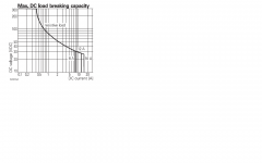
If you look at the relay spec, it shows the DC load breaking curve as displayed below. At 75V, the DC load breaking capability of the relay is about 1.1A, or about 10% of the probable current that flowed during the failure event. This was probably enough to cause the contacts to stick together and blow the speakers.
The lesson to be learned here is that relay DC handling specs really do need to be adhered to. So, I will replace this relay and fix the module up, along with my speakers, but for all new power amp designs, I will go with a different appproach. Many people recommend using an auto relay, but I checked out the DC load switching capability and its not clear that they would reliably switch on a fault condition. I did some research and the Panasonic EP(AEP) series look like they may do the trick - the 10A PCB mount version.
Now, I have to work out why the damn output stage failed in the first place.
My 250 watter blew a channel this weekend . . .and took the bass units out on one of my B&W 703’s. As it went out, there were sparks and noises coming out of the of the amp and then a smell like burnt varnish from the speaker.
I was and still am mightily pissed off.
At first I thought it has the Vbe multiplier that had opened up, but after removing the module and checking the components, it seems an MJ21194, MJE15033 and an MJE15032 blew short. The pre-drivers, VAS and all the small signal components were ok, although the driver emitter resistor was badly burnt (this is a 27 Ohm that connects the two driver transistor emitters together – both drivers were short, so this resistor had 140V across it before it too open circuited). The 0.22 Ohm 7W emitter ballast resistors on the output devices made it though – even on the 21194 device that blew s/c. It looks like the output device failed short, put about 75V across the speaker, causing the bass drivers to fail.
Then I wondered why the MCU based protection controller did not kick in and open the output relays as soon as it detected an output DC condition. I took a look at the relays. Well, one set of relay contacts was ‘stuck’ (i.e. welded) in the closed position and the cover was smoked over in the vicinity of the contacts. So, it looks like the other two relays opened correctly (or dropped out when the power was pulled).
In my wisdom, and against everything I was always told about paralleling relay contacts, I had put 3 sets of relays in parallel (Tyco RP3 16A 250 VAC devices) in the interests of low output resistance. The MCU probably tried to do its job, so relays 1 and 3 opened up as the fault protection kicked in, but the last relay to open up was #2. I don’t know at this stage whether or not the failed contact actually did open correctly, only to succumb to subsequent arcing, or whether it simply stuck because it was well outside the DC load capability.
If you look at the relay spec, it shows the DC load breaking curve as displayed below. At 75V, the DC load breaking capability of the relay is about 1.1A, or about 10% of the probable current that flowed during the failure event. This was probably enough to cause the contacts to stick together and blow the speakers.
The lesson to be learned here is that relay DC handling specs really do need to be adhered to. So, I will replace this relay and fix the module up, along with my speakers, but for all new power amp designs, I will go with a different appproach. Many people recommend using an auto relay, but I checked out the DC load switching capability and its not clear that they would reliably switch on a fault condition. I did some research and the Panasonic EP(AEP) series look like they may do the trick - the 10A PCB mount version.
Now, I have to work out why the damn output stage failed in the first place.
Attachments
Last edited:
Hi. Sad story.......There is one another option.....to use triac protection. Such circuit which short the output ....... Quad 405 has such circuit at later models....and of course leave relay protection there as well.
Those Tyco/Schrack has many contacts so you can connect them in series or parallel.....
http://www.farnell.com/datasheets/573461.pdf
Best regards, Taj
Those Tyco/Schrack has many contacts so you can connect them in series or parallel.....
http://www.farnell.com/datasheets/573461.pdf
Best regards, Taj
Member
Joined 2009
Paid Member
I just had an interesting idea. (lol) One could use an ordinary rela, one set of contacts goes to the amp, the other also goes to the amp, but through a highish ohmed resistor, high enough so that the current the full rails can provide to the speakers can not damage them. This should be a more forgiving error condition than a short to earth.
I just had an interesting idea. (lol) One could use an ordinary rela, one set of contacts goes to the amp, the other also goes to the amp, but through a highish ohmed resistor, high enough so that the current the full rails can provide to the speakers can not damage them. This should be a more forgiving error condition than a short to earth.
wouldnt the current just find another way if you did that?, thought the idea of relay protection was that you provided a path the current would prefer to take than your gear
Hi Bonsai... I can just imagine $%%^
I have the B&W 703's too (have a pdf manual if you want it) so I understand the frustration.
DC protection... we all hope we never need it, when we do will it work ? Nobody ever tests it too (for real) by sticking a screwdriver across an output device and seeing what happens.
Doug Self did a very interesting write up many years ago on this and the opinion was that protection at best may save a potential "fire" due to the coil burning but would not stop damage to the speaker.
Switching (breaking) a high DC current thats flowing in an inductive load is not easy... as you have found out the arc drawn just welds the relay contacts.
There was a very interesting thread (think it was this one) using FET's as a series switch and controlling them with photovoltaic diodes.
http://www.diyaudio.com/forums/solid-state/155939-mosfet-relais.html
Another issue is the integrator time delay on any DC protection scheme and this together with the relay pull in delay introduces anoher issue. This was something I actually looked into but never developed into an actual circuit as yet. The idea was to compare the input and output of the amplifier rather than detect a DC fault and any difference indicates a problem.
http://www.diyaudio.com/forums/solid-state/20745-another-simple-dc-protection-2.html#post2111389
Post #39. Still can't find the original thread...
I prefer a belt and braces and hammock approach, Although I'll be truthful and admit I have never (yet) incorporated all 4 protections in the same amplifier.
Fuse protection of the supply rails after the main smoothing caps.
Current, or preferably IV, limiting that allow high transient currents to pass to reactive load, but limits DC output current to suit the power device SOAR.
DC detect and relay protect the speakers.
Input mute on fault detection.
Other possibles could be Crowbar/Thyristor short across output terminals on fault detection.
MosFET fuses in the supply lines.
Last edited:
DC and relays are generaly not friends, you get relays with two contacts that open sequentialy, the one that makes or breaks the contact is made of tungsten or something.
Auto relays work almost faultlessly in a hostile DC only environment.
You can buy a decent 16A (or higher) contact rating 12V from any auto dealer.
DC and relays are generaly not friends, you get relays with two contacts that open sequentialy, the one that makes or breaks the contact is made of tungsten or something.
Auto (car) relays work flawlessly (for a few years anyway) in a hostile DC environment.
It's easy to obtain 16A - 30A auto relays which are great for speaker protection.
Sorry for the double post - my internet connection is playing up - some bugger riding on the wireless connection I expect.
But it is for Automobile voltage, possibly a maximum of 14.5Vdc
Can this reliably cut a 40Vdc or 50Vdc or 60Vdc current?
Two relays would do it. One to short the output to Audio Ground and the other to open the Output to Speaker terminal route.
They will normally be OK at 50V or so as they will be normally closed.
http:\\www.rs-online.com is a good source of data for all manner of components.
for speaker delay at start up and speaker disconnect just before shut down, any relay is just about OK for normal AC (audio) signals. This may require an input mute to minimise the signal at the output during relay switching.
DC fault current breaking is completely different.
I suspect an Automobile relay will suffer just as badly as the typical example in post1.
DC fault current breaking is completely different.
I suspect an Automobile relay will suffer just as badly as the typical example in post1.
I have always wondered about the small physical size of the relays used on Audio devices compared with the currents they are rated. Here http://www.elkontrol.com/downloads/siemens/59_1.pdf
there is an example of some of the SMALLEST CONTACTORS used in Industrial Automation to control loads of few, single digit Amps.
Similar models are manufactured by many other brands (i.e ABB, BTicino, SquareD, Schneider, just to name a few) an widely available.
Typical Loads are motors and heating resistors, that have a significant inductance, similar to speaker coils. They usually feature 3 or 4 Normally Open power contacts and have options for snap-in additional contacts, R-C networls for arc suprssing, etc. The kind values of power (currents, voltages) used in Audio devices (except in really professional PA devices) should pose no real threat on them, even in seldom fault (rail sticking or output short) conditions.
Problems: they are a little big, very noisy at switching and quite slow.
I have no idea about linearity issues, but I believe they are accettable under that profile.
If you can accept these shortcomings, I believe they could be used as trustful speaker/protection relays.
The problem here is how to handle a clean relay switch over with 75 or so volts across the contacts and in my case about 6 ohms DC resistance. I took the relay out last night and opened it up. The contacts are truly welded together. I stuck a screw driver between the contact surfaces to try to pry them apart. No chance. I've taken a long hard look at this over the last few days and if you want your relay to be able to handle the worst case 'up to your *** in alligators' problem, you really need a good relay.
I looked at the auto relay but they are spec'd for 13.5V and from what I've seen the relay DC specs, the current capability drops off quickly as contact voltage goes up. The Panasonic relays I referred to in my first post look pretty good. Single contact set rated to switch 10 at 100V. They also spec the relay for higher current switching, but with a reduced life.
Tomorrow I hope to get the faulty channel going again. BTW I am also making a few mods based on what I've learned over the last 3 years or so - TMC compensation and improved triple EF parasitic prevention. I no longer have access. To the AP so I 'll have to go back to using a sound card to assess the spec improvements.. On simulation it looks good though - 11ppm at 20KHz full power.
Last edited:
The problem here is how to handle a clean relay switch over with 75 or so volts across the contacts and in my case about 6 ohms DC resistance. I took the relay out last night and opened it up. The contacts are truly welded together. I stuck a screw driver between the contact surfaces to try to pry them apart. No chance. I've taken a long hard look at this over the last few days and if you want your relay to be able to handle the worst case 'up to your *** in alligators' problem, you really need a good relay.
I looked at the auto relay but they are spec'd for 13.5V and from what I've seen the relay DC specs, the current capability drops off quickly as contact voltage goes up. The Panasonic relays I referred to in my first post look pretty good. Single contact set rated to switch 10 at 100V. They also spec the relay for higher current switching, but with a reduced life.
Tomorrow I hope to get the faulty channel going again. BTW I am also making a few mods based on what I've learned over the last 3 years or so - TMC compensation and improved triple EF parasitic prevention. I no longer have access. To the AP so I 'll have to go back to using a sound card to assess the spec improvements.. On simulation it looks good though - 11ppm at 20KHz full power.
Sorry to hear you blew up that nice triple amp on your website.
 I carefully note your failure of the ON semi mje15032/33's
  . I won't use the little MJE's for drivers in my new triple. They might take a little more space , but to go with outputs as drivers "is the way" (2sa1294/sc3263 in my case). With just 3 pair 21193/4's running a Dayton sub , my mje's were quite "stressed".
 I found that I was approaching their SOA on occasion
.TO-3p OP's are nearly as cheap as to-220's these days ($1.80usd) , coupled with the fact that most of the OEM's with fried OP stages I've worked on had driver failure.
A TO-3p as driver is WELL within it's SOA , no matter what hell you expose the output pairs to. They run much cooler , I've even run them without a heatsink for a short period. With a modest heatsink , normal operation is cool even in the hot summer sun.
- Home
- Amplifiers
- Solid State
- Output Relays