I thought that mech relay contacts degrade with age and add distortion, and therefore one of the big reasons to eliminate mech relay contacts from the signal path was to eliminate this distortion with age. Adding one may make the protection more robust, but at a high price?Using both types of relays is supposed to give you the best of both worlds for protection. It looks like they are using the SS relay portion as a speaker outlet selector as well.
Ohooo!! Thanks for the lively exchange, it seems as, though, some clarifying comments are due by me:
- MusicHall had electromechanical relays in both places, power on delay and speaker group selection, resulting in two degrading contacts in a row! This is what I want to modify - more detail in the linked modification thread.
- The SSRs are piggy-backed on the original output assembly, the electromechanical group relays were removed.
- I'm currently planning to further modify the circuitry, so the power on logic also switches the group relays and the electromechanical pwr-on relay can go away, the former contacts can be bridged. But that's a different project - off-topic here...? (...schematic/logic details in the linked modification thread...)
So, my questions to you folks in this thread here are about the four Si8751 schematics (which are the piggy-backed substitutes for two group relays) and their components' electronic dimensioning (drive current, Zener and the like...)
Thanks and Regards,
Winfried
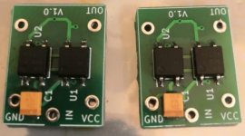
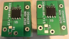
Finally, got the MOSFET SSR PCBs today, I assembled a couple and tested them, they are working fine  tomorrow going to replace Finder relays in my My_Ref Fremen Edition LM3886, it will be a busy day!
tomorrow going to replace Finder relays in my My_Ref Fremen Edition LM3886, it will be a busy day!Attachments
Last edited:
 those are looking good
 Finally, got the MOSFET SSR PCBs today, I assembled a couple and tested them, they are working fine
Nice work!
Can you share gerbers?
Nice work!
Can you share gerbers?
+1 I would love them too so I can try these
Thank you for the warm comments. Actually, without the advice of minek123 who is wise/practical, Mooly who is patient/literate, and Michael Bean who is experienced, this would not have been possible because I had no previous experience with such MOSFET implementation.
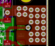
I have been refining the PCB in order to support 8.0A instead of 4.0A for a temperature rise of 8~10°C in copper temperature, I assume the latter is acceptable.
Duplicating the zone connecting the two SOURCE pins of the MOSFET enables higher current support, shifting the MOSFET to the left also allows for a larger zone as well, frankly more than 8.0A. The final PCB design is somewhat different compared to the prototypes, anyway, it doesn't really matter to me as I don't need higher current support for the LM3886.
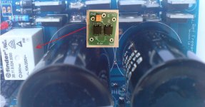
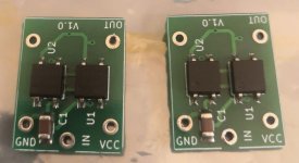
Final prototypes assembly photo is attached, I salvaged those capacitors from an obsolete Aruba wireless controller Couldn't find better use of the board!
I have not decided whether I will publish the Gerbers for the public, or go for a group buy, may be it is too early to go for a group buy at the moment.
I have been refining the PCB in order to support 8.0A instead of 4.0A for a temperature rise of 8~10°C in copper temperature, I assume the latter is acceptable.
Duplicating the zone connecting the two SOURCE pins of the MOSFET enables higher current support, shifting the MOSFET to the left also allows for a larger zone as well, frankly more than 8.0A. The final PCB design is somewhat different compared to the prototypes, anyway, it doesn't really matter to me as I don't need higher current support for the LM3886.
Final prototypes assembly photo is attached, I salvaged those capacitors from an obsolete Aruba wireless controller
Couldn't find better use of the board!I have not decided whether I will publish the Gerbers for the public, or go for a group buy, may be it is too early to go for a group buy at the moment.
Attachments
Adding one may make the protection more robust, but at a high price?
Yeah. The MOSFET-based solutions are a bit expensive, but they provide much better protection than a relay (in addition to also providing lower distortion that does not change with age).
The biggest advantage of the MOSFETs is that, unlike relays, they don't arc over when they break the current to an inductive load. I suggest having a look at this website. The write-up is excellent and there're some spectacular videos of arcing in relays used for speaker protection: Speaker DC protection with relays
Tom
I have not decided whether I will publish the Gerbers for the public, or go for a group buy, may be it is too early to go for a group buy at the moment.
Either way - count me interested and in !
Here’s a SSLR with gerbers Solid State Relay with PCB Layout
It has the same external size as a Tyco relay.
It has the same external size as a Tyco relay.
Here’s a SSLR with gerbers Solid State Relay with PCB Layout
It has the same external size as a Tyco relay.
Thanks Andrew ! I read the other excellent articles on your site but missed this one completely...
Either way, what would be brilliant is a group buy for a bunch of these ready assembled at one of those fab / protoshops ...
- Home
- Amplifiers
- Solid State
- Output Relays