After summer holidays I fix that hum problem by isolating RCA connectors from chassis. Thanks Callmart.
But now there is other problem again. When I play test CD which includes "frequency sweep" from 0Hz to 20kHz some oscillations appears. Not all frequencies but allways on same frequencies.
Wierd? What should I do next?
But there is still some quiet hum when I connect CD-player to amplifier. When I disconnect it, hum disappears totally. If I disconnect amplifier RCA cable shield from RCA connector and CD-player is connected then there is very loud hum?
Previous thread:
http://www.diyaudio.com/forums/show...0&perpage=15&highlight=crescendo&pagenumber=1
 [/
[/
But now there is other problem again. When I play test CD which includes "frequency sweep" from 0Hz to 20kHz some oscillations appears. Not all frequencies but allways on same frequencies.
Wierd? What should I do next?
But there is still some quiet hum when I connect CD-player to amplifier. When I disconnect it, hum disappears totally. If I disconnect amplifier RCA cable shield from RCA connector and CD-player is connected then there is very loud hum?
Previous thread:
http://www.diyaudio.com/forums/show...0&perpage=15&highlight=crescendo&pagenumber=1
[/Eccu said:[snip]But now there is other problem again. When I play test CD which includes "frequency sweep" from 0Hz to 20kHz some oscillations appears. Not all frequencies but allways on same frequencies.
Wierd? What should I do next?
[snip]:[/
What do you mean: oscillations occur? What do you hear? How do you know there are oscillations?
Jan Didden
Sorry my hasty description.
-Jan-
I mean that, when I start to play that "frequency sweep". When "sweep" is between (about) 30-70Hz, sound is…. hmmm how I say…. like square wave (clipping)… I'm not sure is that even oscillation. Then about between 70Hz-150Hz sound is quite clear. etc….
It's quote hard to explain. I can do some additional measurements to clarify this problem if you need.
I can use oscilloscope and signal generator.
Damn… Other (left) channel works nice but this another (right) makes me crazy.
-Rudy-
Yes, I have connect only other channel at time when I test that hum problem. Anyway, that hum problem occurs on both channel.
I will jump to lake!
I'm unlucky or what..... I cannot believe that.....
I tested again both channel and I just noticed after more accurately listening that both channel have some kind clipping effect or so. Sound is not so natural what it supposed to be. Is that possible that green led can cause that because original scheme there is red leds on place D1 and D2?
Or can those T7 and T9 cause this because those are not BC560C and BC550C... but those are BC550B and BC560B?

Should I give up and throw that Crescendo project to dustbin.

This project has been trial for me.... but it is too much for me at the moment... I can't managed to fix it without you help, DIY guys....
I'm unlucky or what..... I cannot believe that.....
I tested again both channel and I just noticed after more accurately listening that both channel have some kind clipping effect or so. Sound is not so natural what it supposed to be. Is that possible that green led can cause that because original scheme there is red leds on place D1 and D2?
Or can those T7 and T9 cause this because those are not BC560C and BC550C... but those are BC550B and BC560B?
Should I give up and throw that Crescendo project to dustbin.
This project has been trial for me.... but it is too much for me at the moment... I can't managed to fix it without you help, DIY guys....
You don't have oscilloscope?
If you have clipping sound atmeduim level, you _can_ have broken driver transistors. I had one BF471 with secondary breakdown around 30 volts. The got nasty over 30 volts peak.
The Crescendo is much of a standrard solution and works very well.
Try to borrow a oscilloscope! If you can measure all currents and voltages it can be a help for us.
If you connect the oscilloscope both the input and the output and compare. Then test with no load and low frequency (1 kHz) and check the waveform. Then connect load, still looking good? Then increase the frequency to max 10 kHz. DON'T test at >100 kHz or above! Do you get oscillations over a certian postive voltage? If yes, increase the gate resistors up to 470 ohms in small steps. You may have oscillating N-channel devices.
Check how much output signal you get. Do you get as much you expect (5-10 volts less than supply voltage)?
If not start to measure currents and voltages in order to determine the working conditions.
Check how much output signal you get. Do you get as much you expect (5-10 volts less than supply voltage)?
If not start to measure currents and voltages in order to determine the working conditions.
Hi Eccu,
as you know I had similar problems with my amp.
They started clipping at 25Vpeak cause the voltage over D3 and D4 wasn´t appropriate.
Check those as well being at it.
And yes, a scope, a sine generator and dummy resistors would be nice to test the amp.
Don´t blow your speakers.
I´ll press my thumbs
Cheers
Jens
Eccu,
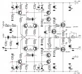
This can take a some time, but edit the file in ... paint or wathever and add the DC values to the schematic.
With this information it is a LOT more easy to help you, and if you could be so kind, change the value on the schematic to the ones you used, if you changed something that is offcourse.
This can take a some time, but edit the file in ... paint or wathever and add the DC values to the schematic.
With this information it is a LOT more easy to help you, and if you could be so kind, change the value on the schematic to the ones you used, if you changed something that is offcourse.
Attachments
I wouldn't worry too much over the LED'. You wíll get slightly higher currents but the main thing is the T7 and T9 get sufficient Vce (not get saturated), becuase this get less with higher currents (unless you reduce R25 and R27).
The red arrows above are good measurement points. If you can give us those we can get a picture of the problem. Using B-models instead of C for BC transistors _may_ need adjustments.
Note also if you have turned a BJT wrong (interchanged collector and emitter) , it works with gain Hfe of 3-10 and max voltage 5-7 volts. Make sure once again that every part is turned right. Can you take a picture maybe?
Hello all.....
It's sad but true that I do not have chance to use just right components what those supposed to be. This because local dealer does not have exactly right values what I need.
1st thing.... Those D3 and D4... I have used 1N4730A zeners which are (3.9V, 1W Zener Diode) so should I change those to 0,5W models?
I start now make some measurements.... be ready")
It's sad but true that I do not have chance to use just right components what those supposed to be. This because local dealer does not have exactly right values what I need.
1st thing.... Those D3 and D4... I have used 1N4730A zeners which are (3.9V, 1W Zener Diode) so should I change those to 0,5W models?
I start now make some measurements.... be ready
Hi Eccu,
about D3,D4...
I used 1.3W zeners and due to too less bias current I had about 2V over them.
If I remember correctly zeners should be "biased" with about 1/10th of Imax so go for 0.5W types or raise current through them.
If the voltage is <3.9V your amp definitely clips before it should.
See here
Good luck
Cheerio
Jens
Thanks Joensd... I have been read that earlier today.
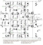
Here are measurements from left channel. Nothing connected to input or output.
So.... over zeners is only 3V.....
Next step is to buy couple zeners
Someday on the next week I will get oscilloscope and I will make some additional measurements of both channel.
Any way... is those other measurements right?
Attachments
Eccu,
here we go,
FIRST OFF ALL, BEFORE DOING ANYTHING MAKE SURE THE BIAS CURRENT OFF THE MOSFETS IS SET TO 0 Amps.
You don't want these babies to be destroyed, there mutch too expensive for this.
1. becouse u use green led's the current through the VAS stage is to high, actually about 50% to mutch, better solve this by changing the led's to red one's ( 3mm ) or by replacing R17 & R20 with 390ohm resistors.
2. Replace the zeners D3 & D4 with 0.5W ( 0.4W ) types, ore if these are hard to get try changing the resistor with some lower value's, like 8K2 or 6K8, still the silution with the 0.5W zeners is the best way.
Well, after all this crank up the bias till 200mA and measure all this again, so we are able to see iff all of this had any effect.
The "rare" soundings in the 50...100Hz region can be the result off the bad current settings off the amp, therefor it was not able to deliver any power to the speakers, this is the region where your speakers demand the most power ( actually < 50Hz ask's more power, but we are not able the hear distortion in this region ).
Good luck and let us know about the results
Greetz Rudy
Hello again...
Very helpful peoples here.... thanks!
I have earlier changed those R17 and R20 from 270ohm to 460ohm because bias was too high.
More about that in this thread below:
http://www.diyaudio.com/forums/show...5&perpage=15&highlight=green+red&pagenumber=2
Yes.... next step is that I will change those zeners.....
Lets hope that is final cure.....
Now I have changed those D3 and D4 zeners from 1W to 0,4W models.... but before I assemble all stuff again together for testing I have few question still open.
Can I replace coax -cable (RCA) which goes from backplate to amplifier board with twisted pair cable. Is there any disadvantages in this kind cable which should carry low level signal?
And should I connect 10ohm resistor and 100nF capacitor in parallel and connect it between to RCA input frame and backplate (ground) ? And will this prevent some ground loop (hum)?
I ask these because every time I have some problem in my amplifier I must disassemble so must stuff before I can do any modifications to boards. At the moment I have been disassemble total four times and its not so funny thing....
- Status
- This old topic is closed. If you want to reopen this topic, contact a moderator using the "Report Post" button.
- Home
- Amplifiers
- Solid State
- Still some problems with Crescendo. Oscillation or what?