Could be a well sounding amp. And still close to Hifi.
After a test today it is a well sounding amplifier....
 It is confirmed by 3 other people now...
Some SPICE Play
Well Sonnya,
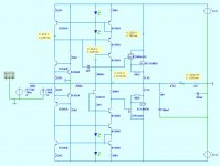
I hope you excuse me, but after the talk in the SSA thread about the sound of 1000V / uS, I had some fun with your very elegant design, which I really like.
I had a vision of having balanced pairs of these taking the current o/p from my Buffalo DAC . . . . but before I got into that I could just try driving into the 100R input resistor from IVY - which can drive headphones.
In real life I would begin with your design and try each mod one at a time see how each change sounded - but there is nothing that revolutionary just regular measures.
I would be interested to compare this with with my DC linked version of Motzilla
cheers
mike
p.s. would probably have regulated + & - 30V for early stages
Well Sonnya,
I hope you excuse me, but after the talk in the SSA thread about the sound of 1000V / uS, I had some fun with your very elegant design, which I really like.
I had a vision of having balanced pairs of these taking the current o/p from my Buffalo DAC . . . . but before I got into that I could just try driving into the 100R input resistor from IVY - which can drive headphones.
In real life I would begin with your design and try each mod one at a time see how each change sounded - but there is nothing that revolutionary just regular measures.
I would be interested to compare this with with my DC linked version of Motzilla
cheers
mike
p.s. would probably have regulated + & - 30V for early stages
Attachments
He! It sounds Like you are going to build a powerdac?!
You could easely use it directly from the dac's current output. It is a good idear to do as you have done. The buffer stage before the exicon lowers the distortion at higher frequency.
In the revised layout i am working on the last days i have added ksc3503 and ksa1381 as a bufferstage, and this at the same time gives lower distortion at lower idle current in the exicons.
I am happy to hear that you would Like to experiment with it.
If it has your interrest it Will be available within a week or two. I would Like to hear your comments too.
I know this section is not comercial but i have paid for such a section and Jason has made All the preparations for it, so it is only me who to find time to get it ready.
Your comments & circuit gave me the idea for powerdac - it's most minimalist so I like the idea.
Also reducing value of FB resistor decreased distortion very much.
I will probably experiment initially with point to point . . .
but for now I will be travelling for 1 month so I look forward to pick this up after I return.
Also reducing value of FB resistor decreased distortion very much.
I will probably experiment initially with point to point . . .
but for now I will be travelling for 1 month so I look forward to pick this up after I return.
contact
Hi Sonny, i also tried to contact you by PM. I know you are busy and maybe you missed my mail about transistors ....
Regards,
Loek
Hi Sonnya,
I have tried to contact you by PM and email, but without luck. Could you please PM me?
mkc
Hi Sonny, i also tried to contact you by PM. I know you are busy and maybe you missed my mail about transistors ....
Regards,
Loek
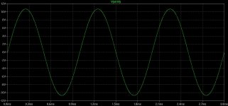
THD measurements.
All THD measurement at 1W the amp is running in class A.
THD at 1KHz@1W is masked by EMI from powersupply.
At 8W the amp is outside class A. The performance at 10KHz and 20KHz is poor seen from the point of view that it is a feedback amp, but the THD falls nicely of.
The amp is not good at at handling crossover distortion which is the reason why distortion is a bit high at 10KHz and 20KHz.
But it is a simple amp which is easy to build.
Attachments
-
simpleamp v11 noninverted 8r 8w 20khz.pdf35.8 KB · Views: 68
-
simpleamp v11 noninverted 8r 8w 10khz.pdf36 KB · Views: 65
-
simpleamp v11 noninverted 8r 8w 1khz.pdf36.1 KB · Views: 84
-
simpleamp v11 noninverted 8r 1w 20khz.pdf35.8 KB · Views: 61
-
simpleamp v11 noninverted 8r 1w 10khz.pdf35.7 KB · Views: 56
-
simpleamp v11 noninverted 8r 1w 1khz.pdf35.8 KB · Views: 105
Your comments & circuit gave me the idea for powerdac - it's most minimalist so I like the idea.
Also reducing value of FB resistor decreased distortion very much.
I will probably experiment initially with point to point . . .
but for now I will be travelling for 1 month so I look forward to pick this up after I return.
Hi Mikelm.
Are you start build your powerdac?
Well, I guess would only ever be a Power I2V converter but I didn't get around to it yet.
I have two amps a loudspeaker to build first.
Have to say purely as a symmetrical amp the SSA captured my imagination.
But ur design did seem most happy when fed with current.
I'll let you know . . .
I have two amps a loudspeaker to build first.
Have to say purely as a symmetrical amp the SSA captured my imagination.
But ur design did seem most happy when fed with current.
I'll let you know . . .
This is going to turn.
We did get it safe, and the sound from it is true "current feedback" profile.
But you are right: the feedback makes it unsuitable for I2V powerbuffer.
I know that Andrej has it running with only +/-20mV drift. I dont knowwhat he did to make that stable, other thenm adding a cascode stage so that the VAS BJT's was less subjected to delta temperature and therefore a more stable vbe drop which again leeds to a more stable idle current.
Secondly he has degraded the VAS stage with 100K||100K.
I would really like to see some "real life" thd figures from it. But i suspect that with this VAS stage degeneration of ~50K it will be quite high.
Third: his gain is down to 16x where we used 21x
Fourth: his idle current is lower in every stage. Therefore less temp. changes in the BJT's
Without the VAS cascode and VAS degeneration we was down a drift of +/-50mV after adding a current source to the inputstage instead of emitters resistors (He fixed this problem more or less with an 1.5K NTC)
After adding a servo the drift is down to +/-1mV.
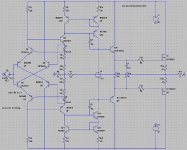
For the last version of my circuit (the last one in this thread) i got really low THD above CLASS A level, by adding a buffer stage before the mosfets. And it is 1/5 of the idle current in the mosfets.
This will be send to production next week.
So end next week i will have the PCB's up and running.
What i hope for this design is that i get really low THD of 0.006% just before clipping . But measurements will tell there story of it.
We did get it safe, and the sound from it is true "current feedback" profile.
But you are right: the feedback makes it unsuitable for I2V powerbuffer.
I know that Andrej has it running with only +/-20mV drift. I dont knowwhat he did to make that stable, other thenm adding a cascode stage so that the VAS BJT's was less subjected to delta temperature and therefore a more stable vbe drop which again leeds to a more stable idle current.
Secondly he has degraded the VAS stage with 100K||100K.
I would really like to see some "real life" thd figures from it. But i suspect that with this VAS stage degeneration of ~50K it will be quite high.
Third: his gain is down to 16x where we used 21x
Fourth: his idle current is lower in every stage. Therefore less temp. changes in the BJT's
Without the VAS cascode and VAS degeneration we was down a drift of +/-50mV after adding a current source to the inputstage instead of emitters resistors (He fixed this problem more or less with an 1.5K NTC)
After adding a servo the drift is down to +/-1mV.
For the last version of my circuit (the last one in this thread) i got really low THD above CLASS A level, by adding a buffer stage before the mosfets. And it is 1/5 of the idle current in the mosfets.
This will be send to production next week.
So end next week i will have the PCB's up and running.
What i hope for this design is that i get really low THD of 0.006% just before clipping . But measurements will tell there story of it.
Like soOOOo. Or not?
It was interesting what Kenpeter proposed, I tried this and here are the results. Not bad at all... at 180mA idle works well too...
Attachments
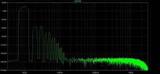
See the difference to my version. There is 30dB less on second and third harmonic.
hm, you have hf switching hiss. it is -180db down @10MHz
in Kenpeter's proposition there is no HF hiss from >10KHz
but anyway I like you project very much
hm, you have hf switching hiss. it is -180db down @10MHz
in Kenpeter's proposition there is no HF hiss from >10KHz
but anyway I like you project very much
My design switches more aprubt than with bipolar.
My gain is 10x higher also
- Status
- This old topic is closed. If you want to reopen this topic, contact a moderator using the "Report Post" button.
- Home
- Amplifiers
- Solid State
- Yet another amp - simple inverted with 10x gain, mosfet output stage