Would it hurt to have the pre-drivers heatsinked in the standard triple? They would get somewhat hot with 20 mA and 35 Volts.
But if it isnt needed I can leave the heatsinking out for the pre-drivers. Probably going with just the standard triple.
I don't understand the point of biasing the pre-drivers at 20mA. Would it be no good if biasing them at 5mA?
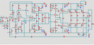
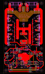
Excellent work on the layout design. I see you handle the Grounds carefully.
It may be unnecessary but I would put a couple of diodes as a means of protection to the output transistors by clamping the output node to within the supply rails in the event of load kicking back. I'd also double up high current tracking by duplicating the traces concerned on the other side of PCB. I myself don't trust PCB shops on copper weight, and I always put big vias along the doubled up traces so that I can solder bus bars if I wish. If possible I'd fit an optional low-pass filter to the input just in case there is trouble.
I don't see over-current protection maybe I missed something?
I don't understand the point of biasing the pre-drivers at 20mA. Would it be no good if biasing them at 5mA?
Excellent work on the layout design. I see you handle the Grounds carefully.
It may be unnecessary but I would put a couple of diodes as a means of protection to the output transistors by clamping the output node to within the supply rails in the event of load kicking back. I'd also double up high current tracking by duplicating the traces concerned on the other side of PCB. I myself don't trust PCB shops on copper weight, and I always put big vias along the doubled up traces so that I can solder bus bars if I wish. If possible I'd fit an optional low-pass filter to the input just in case there is trouble.
I don't see over-current protection maybe I missed something?
Pre drivers do not need 5 mA per se, reducing their bias does not really have much of an effect.
Thanks, try do do the ground as best as I coul, nothing is perfect but think I got a good compromise going.
I dont really believe much in any protection circuit on the amplifier board itself. I prefer relying on offboard DC and speaker protection.
Wrt. double up high current vias, interesting idea, this is only a 50-65 W amp/8 Ohm, that will be used for 8 Ohm nominal speakers with dips down to 4 Ohm(that is confirmed by a test in a German audio mag) so it does not that really nees any huge current capability, 10 A peak would be just fine. The 3 OP's is just to make the output stage transistors coast along and keeping them in their high Hfe area at all time. Also gives the output stage enough grunt to supply 15-20 A peak into resistive loads with completely overloading the drivers and VAS.
Low-pass input filter is a good idea, but my thinking was mounting it between the Input RCA terminals so any problematic noise will stay completely out of the amplifier.
Last edited:
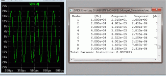
Simulating with the exact same design as my triple EF but just as standard EF", THD-1 is 0.0008%/8 Ohm - 0.0016%/4 Ohm - 0.0043%/2 Ohm and THD-20 is 0.0105%/8 Ohm - 0.016%/4 Ohm - 0.028%/2 Ohm. That is with output power of 50 W/8 Ohm and more or less doubling down to 2 Ohm.
THD-1 is decent enough and more than adequate, THD-20 isnt quite as good but can you hear it? I really dont think it will be much of a problem and I'm not the one chasing absolutely crazy low THD- figues, anything below 0.05 and I'm happy. The reasons for this is twofold, firstly, theres is not much energy at 20 KHz in any music so having high power with crazy low THD isnt that useful, secondly, I cant hear a thing above 17 KHz and lastly(hmm, thats three-fold) humans arent really sensitive in the 15-20 KHz area, even above 10 Khz human aural sensitvity drops like a rock.
Going with a standard EF2 but still with the Ostripper and Sakis recommendations implemented is probably the right way to go.
But getting slightly better THD-20 is not something I would mind if it could be done with relative ease. Any good suggestions?
Last edited:
That location is too far away from the input transistor.Low-pass input filter is a good idea, but my thinking was mounting it between the Input RCA terminals so any problematic noise will stay completely out of the amplifier.
The amplifier performance is dependant on the source impedance seen by the input transistor.
A low pass filter very close to the input transistor is effectively a small C across the base to signal ground. This significantly lowers the HF source impedance seen by the amplifier input.
I recommend a back up (belt and braces) low pass filter at the input socket.
I deliberately choose a very low C value across the socket ~47pF, whereas I choose ~680pF across the amplifier input.
Etch my own ?
Nice looking layouts. I am mostly impressed by single layer routing solutions with minimum jumper counts in tight spaces. Finding a way out of a "dead end " by slapping on an additional routing layer is a good use of board house capabilities. For these kinds of commercial executions I would expect superlative results using an AP hanging on the output.
Nice looking layouts. I am mostly impressed by single layer routing solutions with minimum jumper counts in tight spaces. Finding a way out of a "dead end " by slapping on an additional routing layer is a good use of board house capabilities. For these kinds of commercial executions I would expect superlative results using an AP hanging on the output.
I'm not the one chasing absolutely crazy low THD-
Neither am I. The triple just isolates the VAS , makes it more linear and unaffected by the load. On some of the other topologies , you can shunt compensate or skillfully load the VAS and have these "tricks" remain constant regardless of the load. With large speakers and a EF2 , the VAS can be loaded by as much as 2 ma by the driver bases.
I have an EF2 (actually, 4 of them) I run the VAS at 10ma and use the highest Hfe driver/OP combo I can select. So , I am not "anti -EF2" ... they can sound wonderful and they are simple.
")
OS
Neither am I. The triple just isolates the VAS , makes it more linear and unaffected by the load. On some of the other topologies , you can shunt compensate or skillfully load the VAS and have these "tricks" remain constant regardless of the load. With large speakers and a EF2 , the VAS can be loaded by as much as 2 ma by the driver bases.
I have an EF2 (actually, 4 of them) I run the VAS at 10ma and use the highest Hfe driver/OP combo I can select. So , I am not "anti -EF2" ... they can sound wonderful and they are simple.
OS
Tried to isolate the VAS in an EF2 by using a FET as driver. At 1 KHz the THD numbers are half of the standard EF2 with BJT drivers, but at 20 KHZ the THD is absolutely crap compared to the BJT driver solution. THD-20 at 8 Ohm starts at 0.01 and just goes up from there when going to 4/2/1 Ohm. But it could probably work very well if I use the right FET as a driver and find a solution to the crappy THD-20. But is just an idea, dont know if it is really worth it to go that route.
simplified triple
Made the "magic" triple more DIY friendly. Pick your voltage stage , this one just adds a PPM to whatever your IPS/VAS simulates to (below 1). Killer stable (sim and real) and with a luxman front end does .0003% -.0005% 1-20khz. At 100v p-p , still <.001. I suspect your amp would do 1-2 ppm on it,the blameless with a ccs is the lowest THD front end. Just a idea only..this triple has 2 more transistors + 4 diodes (the 2 CCS's).
PS -this triple only loads the VAS with 27uA @ 2R load. Pre-driver/driver on a separate HS , Vbe on main HS w/ outputs.
OS
Attachments
Thats not bad at all, but think I'll stick with my own EF2, possibly with FET driver(if I can get it to work).
Better keep it somewhat simple for my first amp.
But I do appeciate the willingness to help on this forum even with "basic" questions covered a million times before.
Better keep it somewhat simple for my first amp.
But I do appeciate the willingness to help on this forum even with "basic" questions covered a million times before.
Last edited:
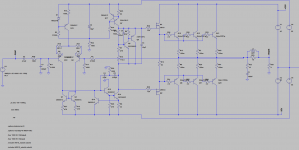
Well, my previously mentioned standard EF2 with all Ostripper and Sakis implementations is now updated with an input filter.
This *should* be my final version.
However getting a FET to work as a driver is something I'll be looking into a little more, luckily that will not require any redesign of the board.
This *should* be my final version.
However getting a FET to work as a driver is something I'll be looking into a little more, luckily that will not require any redesign of the board.
Attachments
I believe and have shown calculated figures supporting my contention that the numbers stack up much worse than 2mA draw on the VAS from an EF2. Further I believe that an EF2 cannot adequately drive a very reactive 4ohm speaker to transients of 40Vpk.With large speakers and a EF2 , the VAS can be loaded by as much as 2 ma by the driver bases.
Some of our amp design experts actually recommend a FET driver and BJT output stage as the best of all the possible combinations.getting a FET to work as a driver is something I'll be looking into a little more,
Some of our amp design experts actually recommend a FET driver and BJT output stage as the best of all the possible combinations.
Do you have an idea as to what FETs would be suitable as drivers?
Last edited:
Well, tried with with irf510/irf9510 as drivers and switched to 2-pole compensation. THD-1 shows a small improvement, but the biggest is the improvement of THD-20.
2-pole compensation might be a little tricky and if I cant get it to work in my amp I can easily just leave out the resistor and 1 cap and go with a standard Miller cap.
So this will be what I am going with.
2-pole compensation might be a little tricky and if I cant get it to work in my amp I can easily just leave out the resistor and 1 cap and go with a standard Miller cap.
So this will be what I am going with.
Attachments
- Status
- This old topic is closed. If you want to reopen this topic, contact a moderator using the "Report Post" button.
- Home
- Amplifiers
- Solid State
- Layout critique