To realize this I know only one way: The use of Light Dependent Resistor and a LED. An example is this device:
http://www.alliedelec.com/Images/Pr.../Silonex-Inc_Actives-and-Passives_6993010.pdf
The question for me is, whether the other characteristic of the internal LDR is comparable to that one of a top quality low noise film resistor. If yes, I have found the ultimate solution without unwanted transition resistances independend of aging and oxidation effects.
The very hugh thread
http://www.diyaudio.com/forums/analog-line-level/80194-lightspeed-attenuator-new-passive-preamp.html
is too long for quickly find out this.
If there are any advices regarded this, please send me the associated post numbers - thank you very much.
Perhaps there are yet additional solutions without contacts in the signal path.
Last edited:
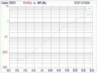
The atch image is Fig 7 (THD+Noise vs. signal level for a NSL-32SR2 configured as a 3 db shunt attenuator with a 2 KOhm source resistance) from the Silonex page at < Silonex Inc.: Products: Audiohm Optocouplers: Audio Characteristics >.
Quickly grabbing two data points, I see 0.010% (-80 dB) THD with -6 dBu input level; and 0.10% (-60 dB) THD with +4.5 dBu input. That's a 20 dB increase in THD for a 10.5 dB increase in input level. Thinking makes my brain hurt, so I will approximate that as a 2:1 ratio. If I recall correctly, that points to a predominantly cubic (third-order) nonlinearity in the photoresistor's V-I curve.
If I re-learned MATLAB I could probably determine the coefficients for a polynomial V-I curve, but maybe somebody who already knows MATLAB will do it.
Dale
Attachments
I don't get this curve...does it mean that the distortion varies with the volume setting or does it mean that the distortion changes with the input level...?? if the latter is the case...it resembles nature i a good way and will thus have a distortion of max 0.025 % at max transient output from the CD (2V).
I believe it shows that THD is a function of input level.I don't get this curve...does it mean that the distortion varies with the volume setting or does it mean that the distortion changes with the input level...??
From the description on the Silonex web site, it sounds like the 32SR2's photocell was connected as the shunt element in a simple voltage divider (L-pad) with a 2 kilohm series element. Then the LED current was adjusted until the voltage divider produced a 3-dB loss. (I think this means the photocell resistance was around 4.8 kilohms.)
Dale
More Applications Information
There is more information about using the Silonex optocouplers as audio attenuators on the Silonex page called "Audio level control with resistive optocouplers". Scroll down to the discussion on the "Shunt Attenuator".
They say that a 3-dB shunt attenuator is a worst-case situation, distortion-wise. I don't know if they REALLY mean "a 3-dB attenuator will give the worst THD, regardless of the series resistance in the attenuator"; or if they mean "the optocoupler has its worst distortion when when the photocell is near the upper end of its usable resistance range". I'd like to see curves for THD versus attenuation for various values of series resistance - e.g., 2K ohms, 600 ohms, 200 ohms, etc.
Dale
- Status
- This old topic is closed. If you want to reopen this topic, contact a moderator using the "Report Post" button.
