Hi,
I've designed a new amplifier based on a Slone amplifier (3 stage topology).
My goal was to use lower noise and SMD components.
Schematic is at here at page 2.
At the moment I've only build the input and VA stage, so everything to the right of the line R4-R47 is not installed on my PCB (except power supply components of course).
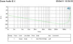
When I measure the amp with an Audio Precision, I get an increase in distortion from 300mV in, while it should readily accept 1V. (see attached plot).
How can I find the source of this distortion? Do need to switch some transistors for a different type?
Thanks in advance.
Kind regards,
Remco Poelstra
I've designed a new amplifier based on a Slone amplifier (3 stage topology).
My goal was to use lower noise and SMD components.
Schematic is at here at page 2.
At the moment I've only build the input and VA stage, so everything to the right of the line R4-R47 is not installed on my PCB (except power supply components of course).
When I measure the amp with an Audio Precision, I get an increase in distortion from 300mV in, while it should readily accept 1V. (see attached plot).
How can I find the source of this distortion? Do need to switch some transistors for a different type?
Thanks in advance.
Kind regards,
Remco Poelstra
Attachments
Hi,
I've designed a new amplifier based on a Slone amplifier (3 stage topology).
My goal was to use lower noise and SMD components.
Schematic is at here at page 2.
At the moment I've only build the input and VA stage, so everything to the right of the line R4-R47 is not installed on my PCB (except power supply components of course).
When I measure the amp with an Audio Precision, I get an increase in distortion from 300mV in, while it should readily accept 1V. (see attached plot).
How can I find the source of this distortion? Do need to switch some transistors for a different type?
Thanks in advance.
Kind regards,
Remco Poelstra
Remco,
It seems that your amp clips at 800mV in. If you know your max Vout and divide by the gain you should get at 800mV. Also, this is most probably VRMS so 800mV is really 1.12V peak.
Does that help?
Edit: I saw your gain is about 30 and your supply about 33V so the max Vin is expected to be about 1.1V peak, which fits.
Of course the distortion will go up a bit before that, and you see that in the graph.
BTW I will visit Duran this Friday with the AES; will you be there? We can take a look if you want.
jan didden
Last edited:
I try to get a 20dB overhead between clipping and normal maximum output voltage.
If you clip at ~30V then normal maximum of 3V is @ -20dB.
Most CDP are ~2Vac and ~3Vpk at maximum signal. Even an overhead of 12dB will keep your normal maximum signal well clear of the distortion rise when output exceeds ~15V.
But this overhead is applied to source and line level gain stages.
In a Power Amp, we don't have that luxury of overhead above normal maximum. We rely on feedback to reduce stage distortion as the power amp approaches clipping.
Yes, it clips at about 800mV at the moment. I'm concerned about the rise in distortion between 300mV and 800mV. I had expected a more sharp changeover from decaying to rising distortion at clip level.
I think your graph shows a typical behaviour for the type of circuit.
Let's talk Friday!
jan didden
I do not fully understand your posting about the overhead.
But does the overhead matter in this case? Whatever the optimum input signal is, I think it's strange, or at least unwanted, that it starts to distort disproportional before clipping.
Some transistor must have a hard time in that circuit and I wonder which one and why") .
.
But does the overhead matter in this case? Whatever the optimum input signal is, I think it's strange, or at least unwanted, that it starts to distort disproportional before clipping.
Some transistor must have a hard time in that circuit and I wonder which one and why
.Then I think you had it right from post #1, try switching some transistors to see what moves! I am so used to seeing the type of curves you showed when looking at audio power amplifiers, that I never bothered to determine if it is one stage or two stages of distortion or even an artifact of the transistors construction.
- Status
- This old topic is closed. If you want to reopen this topic, contact a moderator using the "Report Post" button.
- Home
- Amplifiers
- Solid State
- Large signal distortion in pre/VA stage