Hello
I remember the very good sound of the first Denon PMA-700 amp from the 80's, in those time I never seen the schematic and can't find the first version schematic of that amp.
But I have the PMA-700AE schematic, what is the differences between the PMA-700 amp from the 80's schematic and the recent PMA-700AE schematic ?
Thank
Bye
Gaetan
This looks like the new one:
http://www.hifiengine.com/manuals/denon/pma-700ae.shtml
Isn't this the old one:
http://www.hifiengine.com/manuals/denon/pma-700v.shtml
http://www.hifiengine.com/manuals/denon/pma-700ae.shtml
Isn't this the old one:
http://www.hifiengine.com/manuals/denon/pma-700v.shtml
Last edited:
This amplifier use Denon s generic schematic that consist
of three serial connected differentials, the first one at the
input using jfets.
Performances of this design are better than both the usual
single differential as in the blameless and the dual serial
differentials as used in Hitachi or its numerous copy ala goldmund.
As an exemple of that Denon s lineup, the POA3200.
Attachments
Last edited:
This looks like the new one:
Denon PMA-700AE | Owners Manual, Service Manual, Schematics, Free Download | HiFi Engine
Isn't this the old one:
Denon PMA-700V | Owners Manual, Service Manual, Schematics, Free Download | HiFi Engine
Hello
I've look at that pma-700v page, it is a quite recent version.
Thank
Bye
Gaetan
Hello
I remember that there was an article in the audio magazine La Revue du Son and wroted by Jean Hiraga in the early 80's , the Denon PMA-700 was tested with a spectrum analyser, the thd spectrum was mostly 2 nd and 3 rd harmonic with no high frequency thd harmonics, doing spectrum analyser tests was quite new in a audio magazine in the early 80's. In those years most transistors amps was not so good.
I was just currious to see the first PMA-700 and see why this amp was so good.
If I understand correctly, the PMA-700V are the same schematic than the first PMA-700 ?
Thank
Bye
Gaetan
Last edited:
The "V" probably signified "video", as the amp has the capability of 2 video line ins (stereo audio + composite video signal over rca) selectable via switch.
Here some infos on the 700V:
DENON/COLUMBIA PMA-700V
The older 700Z was released 10 about 10 years earlier.
DENON/COLUMBIA PMA-700Z
The (realtively) new 700AE is another build.
What they all have in common, apart the "700" is still a mistery to me.
Here some infos on the 700V:
DENON/COLUMBIA PMA-700V
The older 700Z was released 10 about 10 years earlier.
DENON/COLUMBIA PMA-700Z
The (realtively) new 700AE is another build.
What they all have in common, apart the "700" is still a mistery to me.
Hello
I've done a quick look at the PMA-700AE, the PMA-700Z and the PMA-700V schematics.
The PMA-700Z are the one made arround 1979, today it would be a classic circuit but in the late 70 it was quite something.
The PMA-700AE are much more recent and it have a more refine fet input front end in the power amp section and a better power supply.
The PMA-700V are very different, there is no LTP in the front end in the power amp section but it use Ic's, and it also have a better power supply. I don't really like the use of Ic's in the front end of an amp.
Bye
Gaetan
Attachments
Last edited:
The PMA-700V are very different, there is no LTP in the front end in the power amp section but it use Ic's, and it also have a better power supply. I don't really like the use of Ic's in the front end of an amp.
If you look carefully, you ll see that this is also a triple serial
differential topology with jfet input differential.
The ICs are there for biaising purposes , not amplification.
Looks like a variable output stage VBE biaising , surely
to obtain a non switching behaving power stage.
If you look carefully, you ll see that this is also a triple serial
differential topology with jfet input differential.
The ICs are there for biaising purposes , not amplification.
Looks like a variable output stage VBE biaising , surely
to obtain a non switching behaving power stage.
Hello
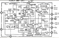
Here is the schematic of the amp section of the PMA-700V, there is no jfet.
Bye
Gaetan
Attachments
Hello
Here is the schematic of the amp section of the PMA-700V, there is no jfet.
Bye
Gaetan
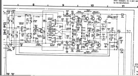
This is the power stage and IC based biaising circuit , the input part is on the left , you can see the full power amp section on page 17 of this PDF.
")
This is the power stage and IC based biaising circuit , the input part is on the left , you can see the full power amp section on page 17 of this PDF.
Hello
There is no pages number in my service manual file, it's cut on the right, but I finally found the fet input section, your right, sorry my mistake.
Thank
Bye
Gaetan
Hello
There is no pages number in my service manual file, it's cut on the right, but I finally found the fet input section, your right, sorry my mistake.
Thank
Bye
Gaetan
Hi gaetan8888, two pages before the one you cropped is page 17.
So what do you mean: is a reparation of my PMA700V worth the hassle (balance pot completely dead)?
Or just retire it and switch to something more "contemporary"?
Hello portomomo
The Denon PMA700V still a very good amp, not all "contemporary" do sound very good.
If you decide to fix the balance pot, maby you can replace the electrolytic capacitors in the power supply, those type of capacitors tend to go dry after years of use.
Bye
Gaetan
The Denon PMA700V still a very good amp, not all "contemporary" do sound very good.
If you decide to fix the balance pot, maby you can replace the electrolytic capacitors in the power supply, those type of capacitors tend to go dry after years of use.
Bye
Gaetan
Hi,
You are pretty much off base here.
The Biasing is not done by the IC's, it uses a normal VBE multiplier (TR501/502). The power stage is unity gain.
The Op-Amp's appear to form some kind of crazy error correction for high frequencies only (IC7 and IC 8 respectively) plus feedback loop for AC only (IC5) that encloses the power stage. It seems unable to work correctly at high levels if there is a significant difference between the channels as well, as the available voltage swing will be way exceeded, due to using a dual op-amp with bootstrapped supplies shared between channels.
I am not sure I would hold this circuit up as paragon of good design next to (say) a Hitatchi lateral Mosfet Amp or the improved versions. I am equally unsure all this shebang is really better than just putting the output stage into the line stage feedback loop (good reasons for that), or letting it run open loop with some slightly less convoluted error correction (good reasons for that).
The power stage is preceded by a very high gain and output voltage line-stage with a tone control in the feedback loop. The line-stage has the kind of circuit you described (triple differential - good for tons of NFB and many zeros after the THD decimal point, less so possible for transient response and TIM/PIM and others like them), however it is a fully stand alone discrete Op-Amp including emitter follower output stage and not really part of the power amp.
Ciao T
This is the power stage and IC based biaising circuit , the input part is on the left , you can see the full power amp section on page 17 of this PDF.
You are pretty much off base here.
The Biasing is not done by the IC's, it uses a normal VBE multiplier (TR501/502). The power stage is unity gain.
The Op-Amp's appear to form some kind of crazy error correction for high frequencies only (IC7 and IC 8 respectively) plus feedback loop for AC only (IC5) that encloses the power stage. It seems unable to work correctly at high levels if there is a significant difference between the channels as well, as the available voltage swing will be way exceeded, due to using a dual op-amp with bootstrapped supplies shared between channels.
I am not sure I would hold this circuit up as paragon of good design next to (say) a Hitatchi lateral Mosfet Amp or the improved versions. I am equally unsure all this shebang is really better than just putting the output stage into the line stage feedback loop (good reasons for that), or letting it run open loop with some slightly less convoluted error correction (good reasons for that).
The power stage is preceded by a very high gain and output voltage line-stage with a tone control in the feedback loop. The line-stage has the kind of circuit you described (triple differential - good for tons of NFB and many zeros after the THD decimal point, less so possible for transient response and TIM/PIM and others like them), however it is a fully stand alone discrete Op-Amp including emitter follower output stage and not really part of the power amp.
Ciao T
The Biasing is not done by the IC's, it uses a normal VBE multiplier (TR501/502). The power stage is unity gain.
Is not the "crazy error correction" also biasing ? It is just active at Xover and at device turnoff. Error correction = bias correction. This is the same idea as nikko's 4 transistor/germanium diode setup , JVC's "super A" . Thread is here ..
http://www.diyaudio.com/forums/solid-state/162559-new-class-super-non-switching-need-revival.html.
Tanaka (sansui) , calls this " a new biasing circuit for class B operation"
OS
Hi,
Normally Bias is considered to be a "static" thing. The error correction changes the AC behaviour. I guess the terminology is open to debate, as a traditionalist I stick to "Bias = DC" and "Error Correction = AC".
The Denon Implementation seems overly complex and in some areas ill considered. If all we want is to prevent turn-off of the halve of the output stage that is not delivering power to the load, there are much simpler, easier and at least as effective methodes.
If we genuinely want to correct the actual linearity of the output stage it does not work well and needs the addition of a feedback loop as actually shown.
Sure, there used to be another one of these "squaring the circle" approaches every other week in the 70's and 80's. They generally worked about as good as any of them.
Ciao T
Is not the "crazy error correction" also biasing ? It is just active at Xover and at device turnoff. Error correction = bias correction.
Normally Bias is considered to be a "static" thing. The error correction changes the AC behaviour. I guess the terminology is open to debate, as a traditionalist I stick to "Bias = DC" and "Error Correction = AC".
This is the same idea as nikko's 4 transistor/germanium diode setup , JVC's "super A" . Thread is here ..
http://www.diyaudio.com/forums/solid-state/162559-new-class-super-non-switching-need-revival.html.
The Denon Implementation seems overly complex and in some areas ill considered. If all we want is to prevent turn-off of the halve of the output stage that is not delivering power to the load, there are much simpler, easier and at least as effective methodes.
If we genuinely want to correct the actual linearity of the output stage it does not work well and needs the addition of a feedback loop as actually shown.
Tanaka (sansui) , calls this " a new biasing circuit for class B operation"
Sure, there used to be another one of these "squaring the circle" approaches every other week in the 70's and 80's. They generally worked about as good as any of them.
Ciao T
- Home
- Amplifiers
- Solid State
- about the Denon PMA-700 amp