I finally got around to pulling the old dead Model 250 Marantz off of the shelf from where it sat for over a decade. Always a Marantz fan, I had purchased this one with know issues as a project box.
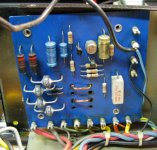
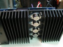
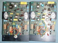
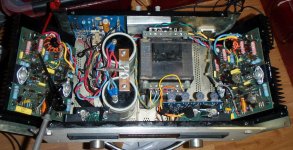
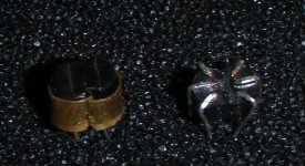
The finals of both side were blown (along with the fuse of course) and so was the original protection circuit (which sucked anyway). It was actually unrepairable as the previous owner had performed some hideously bogus rework. Also, all of the power resistors were way out of tolerance. I'm not quite sure how much that matters (e.g., should be 39 - but actually reads 45 ohms), but they were cheap enough, so I replaced them all (with metal film versions which are much smaller in size) along with the 4 electrolytics. While doing that I found one of the original issues. Both amps had weak solder work originally done to the mid-stage transistors with the star heat sinks. 2 of the three legs were detached from the board like cold solder joints, but they may have experienced 'out-of-spec' operations and melted. I'm not sure as I am rarely there when it breaks. The parts are difficult to replace, but measured OK so I put them back in. Curiously too, there is a diode under one of them that is not in any schematic I have. The finals I substituted for the blown TO-3's are ON Semi - MJ21193G & 94G. They may be over-kill, but they seem to perform adequately and are cheap. I bought a bunch and matched the HFe as best I could.
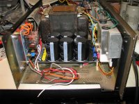
No point to replacing the main PS filter caps or protection circuit with OEM, but not doing so means I needed a board that had filter caps and the full-wave rectifier bridge. I bought a Chinese rectifier/filter board off ebay along with an IC based protection board for the speakers. Anything has to be better than the OEM circuit. The replacement seems to work just fine. She's cranking now.
The finals of both side were blown (along with the fuse of course) and so was the original protection circuit (which sucked anyway). It was actually unrepairable as the previous owner had performed some hideously bogus rework. Also, all of the power resistors were way out of tolerance. I'm not quite sure how much that matters (e.g., should be 39 - but actually reads 45 ohms), but they were cheap enough, so I replaced them all (with metal film versions which are much smaller in size) along with the 4 electrolytics. While doing that I found one of the original issues. Both amps had weak solder work originally done to the mid-stage transistors with the star heat sinks. 2 of the three legs were detached from the board like cold solder joints, but they may have experienced 'out-of-spec' operations and melted. I'm not sure as I am rarely there when it breaks. The parts are difficult to replace, but measured OK so I put them back in. Curiously too, there is a diode under one of them that is not in any schematic I have. The finals I substituted for the blown TO-3's are ON Semi - MJ21193G & 94G. They may be over-kill, but they seem to perform adequately and are cheap. I bought a bunch and matched the HFe as best I could.
No point to replacing the main PS filter caps or protection circuit with OEM, but not doing so means I needed a board that had filter caps and the full-wave rectifier bridge. I bought a Chinese rectifier/filter board off ebay along with an IC based protection board for the speakers. Anything has to be better than the OEM circuit. The replacement seems to work just fine. She's cranking now.
Attachments
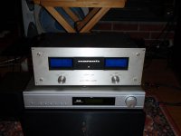
Right Jaycee. I had considered it. In fact I have the parts for a F5 and no case yet. Unfortunately this Marantz wont house the transformer for the F5. Still, I had nothing against the sound of the Marantz amp. I am using it to drive a pair of old AR3a's which are 4 ohm speakers and this thing really does a fine job with them.
As an engineer I can appreciate the 'restore to pristine' or original - only so far. Although no longer original, I think what I have done to this thing makes it a better amp, but not necessarily different (except for whatever impact the finals substitution restulted in). It certainly has a higher quality power supply down stream of the transformer and the old protection circuit is probably the root cause of why I got the unit damaged in the 1st place, so that is better now - although with 60 volt rails I am operating at the extreme end of the protection IC's ability and I have had it go into protect a few times immediately after power-up. So there may be some tweaking to be done there. These IC protect boards (kit) from China come designed for 24V and you have to make changes to a few parts for other rail voltages - as I have done based on the IC data sheet.
As an engineer I can appreciate the 'restore to pristine' or original - only so far. Although no longer original, I think what I have done to this thing makes it a better amp, but not necessarily different (except for whatever impact the finals substitution restulted in). It certainly has a higher quality power supply down stream of the transformer and the old protection circuit is probably the root cause of why I got the unit damaged in the 1st place, so that is better now - although with 60 volt rails I am operating at the extreme end of the protection IC's ability and I have had it go into protect a few times immediately after power-up. So there may be some tweaking to be done there. These IC protect boards (kit) from China come designed for 24V and you have to make changes to a few parts for other rail voltages - as I have done based on the IC data sheet.
Marantz Model 250 Amp rebuild
The final stage transistors are viewable in my post & picture above. I did not need to replace any of the transistors on the actual board, but I did find 'solder anomalies', like weak joints that might have been heat cycled during whatever event resulted in the original death. Re-soldering was all that seemed necessary. Inspect them closely. In this circuit it appears as if the finals take most, if not all the abuse. Suitable substitutions are easily obtainable, but I found a significant variance among them as far as Hfe was concerned. It might not actually matter, but with the 2 of them wired in parallel as they are, I thought it worthy to make a minimum effort to balance them. Buy more than you need and measure / sort them.
The filter board I used is still available from ebay: (search on "10000UF 80V Filter") You need one that goes near 80V because of the high DC rails in this power supply design:
http://www.ebay.com/itm/10000UF-80V...233?pt=LH_DefaultDomain_0&hash=item3cba7475a9
The protection circuit I substituted was also an ebay item ("stereo speaker protection kit"):
OMRON Relay Stereo Speaker protection kit DIY FC1237 | eBay
It has to be modified slightly. The supply resistor needs to be changed to accommodate the higher than expected supply voltage of the AC input and I chose to increase the start up delay slightly (larger capacitor) - and probably not big enough. Sometimes (rarely) the circuit goes into protection immediately upon engaging. Over all, I find this circuit to be a little on the defensive side, frequently popping into protection when inputs are changed - but actually this is a good thing as I believe this is also representative of one of the frailties of this amp design (not too tolerant of abuse). I do have to admit that I often run this AMP at near full power now into a bank or 4 ohm AR-3a's and absolutely love the sound in a huge room. It has never tripped into protection with music playing, just when input transients are experienced like sometimes happen when bringing the system up. I would do it again this way. Sorry to say but the original protection circuit board belongs where it now resides - at the recycle center.
Another Marantz 250 repaired here...
Marantz 250 repaired here...")
A friend asked for help after a bad fleabay buy...
(self-combustion on first try...)
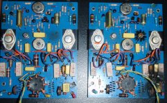
He got another (240) for parts, so I took the best boards and checked everything...
Lots of dead semiconductors in both amps :-(
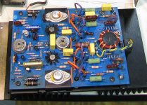
Zener diodes replaced with 2x 9,1V in series, diff-pair with matched BC-5x7,
+ some new caps.
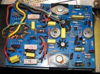
All outputs were gone also, matched 15011/12 is now installed, 3,3 ohm added on base. 0,15 ohm replaced w. 0,27 ohm for safe measure.
Arne K
Marantz 250 repaired here...
A friend asked for help after a bad fleabay buy...
(self-combustion on first try...)
He got another (240) for parts, so I took the best boards and checked everything...
Lots of dead semiconductors in both amps :-(
Zener diodes replaced with 2x 9,1V in series, diff-pair with matched BC-5x7,
+ some new caps.
All outputs were gone also, matched 15011/12 is now installed, 3,3 ohm added on base. 0,15 ohm replaced w. 0,27 ohm for safe measure.
Arne K
Attachments
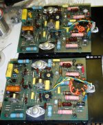

Looks like you used the 240 boards for the repair. So, what happened to that 240 front end? I've seen damage like that to the final stage, but never anything like that to the front end. Perhaps a part failed in the feedback network?
Using the 15011/12's I'd have stayed with the OEM emitter resistors (actually that IS what I did to mine). Doubling them will affect the damping factor I would think, but if you are not the listener, then I'm sure the owner will be pleased to have it working just the same.
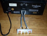
If you left the speaker terminals original, then the fault may return, as I believe that is (one of) the Achilles heal for this amp & non-technical operators. It's just too easy to short the outputs with dogs or kids pulling on poorly-stripped, twisting wires.
Using the 15011/12's I'd have stayed with the OEM emitter resistors (actually that IS what I did to mine). Doubling them will affect the damping factor I would think, but if you are not the listener, then I'm sure the owner will be pleased to have it working just the same.
If you left the speaker terminals original, then the fault may return, as I believe that is (one of) the Achilles heal for this amp & non-technical operators. It's just too easy to short the outputs with dogs or kids pulling on poorly-stripped, twisting wires.
- Status
- This old topic is closed. If you want to reopen this topic, contact a moderator using the "Report Post" button.
- Home
- Amplifiers
- Solid State
- Marantz Model 250 Power Amp repair