It works!!!!!!! Thanks to everyone here for the help!
I don't know if I should be running on 9 v and the schematic didn't even specify AC or DC but listened for about 1/2 hour. So nice to hear something of a flat FR that I thought it sounded great as is. But more critical listening seemed to add extra reverb/ echo, some HF hash, and an unnatural edge to the leading edge of transients. Going back to just a volume pot gave a smoother, more natural sound but not as balanced, frequency response wise. Sort of like CD's vs. records for the smoothness issue.
My setup is a 25K TDK passive volume pot with remote control board which can run on 5.5-26 VDC. Although it did not work for me with 4 AA batteries while a single 9 volt was enough.
"Control central" was to include the tone control on the same PS. Parasound said their Zamp does not have enough power to tap off it to run the TDK motor at 80mAh when changing volume although the 12mA in standby was okay. So certainly not enough to add a tone control which requires continuous power - according to Parasound.
* Can I just add a second 15 VDC wall-wart and wire it like the 9 volt batteries? Is there an easier way?
* What about better op-amps - could they be the cause of the worse sound or is it endemic to ANY tone control?
Thanks again.
Try NE5532 opamps instead of the TDA2320A. That should be quite an improvement.
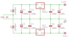
If you want to mains power and dont want to wire a transformer yourself, look for a wallwart with an AC voltage output - they're not as common but can be found. You can then make a regulator circuit like the picture attached - stripboard will do.
You can probably also find a suitable circuit pre-made on eBay, such as this
Attachments
* Can I just add a second 15 VDC wall-wart and wire it like the 9 volt batteries? Is there an easier way?
* What about better op-amps - could they be the cause of the worse sound or is it endemic to ANY tone control?
Thanks again.
Yes two 15VDC supplies will work when wired like the batteries. Order some op amps with them and you can play with what you like. TL072, NE5532 and some others are not very expensive and will give you an idea of how much difference a single chip can make.
I'm not sure if the NE5532 will fit in the same holes as the TDA
http://www.datasheetcatalog.org/datasheet/stmicroelectronics/2289.pdf
http://download.siliconexpert.com/pdfs/op_amp/phi/ne_se5532_a_sa5532_3.pdf
http://www.datasheetcatalog.org/datasheet/stmicroelectronics/2289.pdf
http://download.siliconexpert.com/pdfs/op_amp/phi/ne_se5532_a_sa5532_3.pdf
How do you find what on the PCB ? The zeners ?
Yes, in the Zamp
If the PCB isn't labelled then look for the resistors R228 and 229 which being 2 watt rating will be larger than most of the others. The zeners connect to these so just measure with your meter to check you have located the correct end of the resistors (with 15 volts on them) and take the supply from there. Connect the ground (0 volt line) of the tone control to an appropriate point in the amp. There is probably a star point or similar on the PCB.
Thanks again everyone for the help.
I will give you an update once I try the new op-amps. I will go with 2 15VDC wall-warts for P-S as I need one for the motorized pot (can't run off the power amp) and this is easier than getting a circuit board /enclosure etc.
Be careful with the actual voltage of these wall warts. Typically they are not regulated and specified at nominal load (i.e. 15 Vdc at 1 A load or whatever).
With a light load, such as yours, an unregulated 15 Vdc wall wart might put out 20 Vdc or more.
Hi Discrete, thanks for the tip. I've got part 70235k97 from McMaster-Carr
I measure 15.57 volts when I plug it into the wall with no load. So this looks okay.
Maybe once I get the boost defined, I will take out the pots and use a discrete resistor instead. In any case, this thing is much better than the Behringer DEQ2496 that I tried first. That thing killed the life in the music and added a veil over everything. While this tone control only has 3 bands so is limited in adjustments, it only deteriorates parts of the music. Like more HF hash.
Besides I don't see that a 4dB boost at 160 and then a 10 dB cut at 200 is really good for the driver anyhow. So who needs that much control?
When you're going 'active' and you want a quick , dirty simple electronic crossover , that's how we do ...Besides I don't see that a 4dB boost at 160 and then a 10 dB cut at 200 is really good for the driver anyhow. So who needs that much control?
")
I got the new Op-amps but could use some suggestions on how best to remove the old ones. The holes are really small and close together and I don't want to de-laminate the board from overheating. I got some desoldering braid which has not worked too well in the past - although better than one of those suction plungers. That did not work at all.
While I'm changing things, would also like to change to hi-pass on the input. Using this equation:
Cap = 1/(2 x PI x R x Fc) R
I think it is set at about 12.9 hertz now. I would like to increase that to 25-30 hz as my speakers aren't designed to go below 35-40 hz right now and no sense in over-driving them with frequencies they cannot reproduce.
So for hi-pass of 30 hz, R would be 24K??
Solder wick is still the best way. It does age and tarnish though. Make sure it is clean copper, a bit of flux wont go amiss.
If you are scrapping the old op-amps, just cut through their legs with a Hobby Knife and remove each pin one at a time. Fit sockets and the problem goes away.
If you are scrapping the old op-amps, just cut through their legs with a Hobby Knife and remove each pin one at a time. Fit sockets and the problem goes away.
- Status
- This old topic is closed. If you want to reopen this topic, contact a moderator using the "Report Post" button.
- Home
- Amplifiers
- Solid State
- Is 15-0-15 supply A/C?