A little help please:
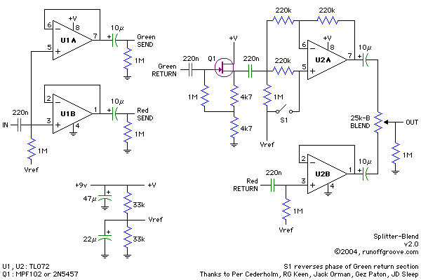
"The Splitter-Blend provides two buffered parallel effects loops with a Blend control. Also, a phase polarity switch is included to allow phase matching of the effect loops."
I've built the above with some minor value changes; it all works apart from the reverse phase switch S1 part of the circuit, Top right
S1 is supposed to reverse the phase of the upper channel; but I find closing S1 kills the channel dead!
All resistor values are as shown,
For the 220n caps I used 330n
For the 10u electrolytics I've used 4u7 MKP
For the Vref part of the circuit I used 33k resistors and 470u capacitors (I've assumed the caps are purely for smoothing so the larger value would make no difference)
12V supply,
Switch open U2A pin 5 = 5v,
Switch closed U2A pin 5 = 6v
I've been all over my circuit and I'm sure it's built right.
Can anyone sugest what the problem might be; or what else I should check?
Original circuit found here: Splitter-Blend
Phase reverse circuit based on: Polarity Reverser
It would make it much easier to help you if you would id number your parts (R1..., C1..., etc)
You are shorting the AC signal path to ground (through the 22uF cap) by closin S1 to Vref. S1 is wrongly hooked up to accomplish what you want it to do
E
PS: It is not the "phase" you are trying to invert, but the "polartity"
You are shorting the AC signal path to ground (through the 22uF cap) by closin S1 to Vref. S1 is wrongly hooked up to accomplish what you want it to do
E
PS: It is not the "phase" you are trying to invert, but the "polartity"
Switch open U2A pin 5 = 5v,
Switch closed U2A pin 5 = 6v
Doesn't sound correct. It should be VREF (6V) in both cases. Sounds like a microamp of unwanted DC offset current is flowing in the 1M bias resistor.
Does the waveform on U2A pin 6 look sane (on a 'scope)? With S1 open, is the DC level on U2A pin 6 sensible?
If it's quick and easy, why not grab a half dozen examples of U2 and swap them in, one by one? Maybe you've accidentally got an especially leaky U2 in your current prototype. (Or maybe your circuit accidentally requires leakage far less than U2's worst case spec)
I got more pin data this morning and the answer jumped out at me:
Pin x = S1-Open/S1-Closed
VRef = 6.2/6.2
Pin 4 = 0.0/0.0
Pin 8 = 12.4/12.4
Pin 1 = 6.2/6.2 Pin 7 = 6.2/6.2
Pin 2 = 6.2/6.2 Pin 6 = 6.2/6.2
Pin 3 = 5.7/5.7 Pin 5 = 5.2/6.2
No potential difference between pins 6 and 7 and it meterd out as a dead short; I couldn't see anything wrong but reflowed the solder on those tracks and it metered right. plugged it all back in and it's working fine.
Thanks for your help and sorry for not doing the basics first!
Glad to hear you got the problem sorted out.
The circuit design uses rather large values of resistance, which means that your scope probe's (or voltmeter's) input impedance will actually load down the circuit and change its operation. I think this may be the reason why your new measurements of U2B are so goofy (Vpin2 not equal Vpin3?? and the circuit is "working"?? -- not possible!) The impedance at pin 2 is less than 1 ohm so your probe has no effect on the measurement of Vpin2. But the impedance at pin 3 is about 1 megohm so your probe has a non-negligible effect on the measured Vpin3. Cowanunga!
The circuit design uses rather large values of resistance, which means that your scope probe's (or voltmeter's) input impedance will actually load down the circuit and change its operation. I think this may be the reason why your new measurements of U2B are so goofy (Vpin2 not equal Vpin3?? and the circuit is "working"?? -- not possible!) The impedance at pin 2 is less than 1 ohm so your probe has no effect on the measurement of Vpin2. But the impedance at pin 3 is about 1 megohm so your probe has a non-negligible effect on the measured Vpin3. Cowanunga!
- Status
- This old topic is closed. If you want to reopen this topic, contact a moderator using the "Report Post" button.
- Home
- Live Sound
- Instruments and Amps
- Help please with OpAmp circuit - Guitar Signal Phase Reverse