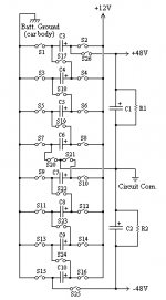
Normal switching supplies for car amps are almost impossible for audiophiles like me to design and build, so I was wondering if this idea would work. It wouldn't be as cost-effective or compact as a traditional regulated switching supply of equal output, but it would be just as efficient and much simpler in design. It would be unregulated, could be used with any voltage, as long as the caps can hangle it, to step up or down, like a transformer, and would even provide isolation. The switching rate would probably be much slower than other switching circuits. S1-S26 would actually be switching MOSFETs of BJTs, but I used switches in the diagram for clarity. To operate, S1-S16 would close, while S17-S26 would remain open, allowing C3-C10 to charge in parallel. S1-S16 would then be opened and S17-S26 would close putting C3-C10 in series and connecting them to C1, C2, and the output supply rails. C1 and C2 would have to be large enough to maintain power on the "secondary" side while C3-C10 are charging, and C3-C10 would also have to be quite large in value, depending on the switching frequency, to keep things going smoothly. Fortunately, C3-C10 would only have to be of the 16V variety. Charging current would have to be at least twice RMS current for all the capacitors to keep it all powered up at full load. C3-C10 may have to collectively handle about 200A peak if the circuit had to supply power for a very large amp. It would be nice if dual layer electrolytics could be used, but the ESR is far too high.
Here's the basic schematic:
Here's the basic schematic:
Attachments
It may be much simpler to construct if you use a conventional type multiplier circuit using diodes. Then you need only two power transistors. The advantage of your way should be that your capacitors can be smaller and the transistors don't have to carry as much a piece. But, it is actually easier to build one which uses a transformer.
Did you find this online or did you think of it? I am not sure how the polarities on all the transistors will work out. I am not sure if the BJTs would be reversed biased and breakdown or short it out through the body diodes in mosfets.
Did you find this online or did you think of it? I am not sure how the polarities on all the transistors will work out. I am not sure if the BJTs would be reversed biased and breakdown or short it out through the body diodes in mosfets.
Why not use one step up circuit with one inverter to supply the +/- voltage to the amp?
It would be easier than make a transformer if you consider you will need only two inductors. Depending on the power and frequencies needed you will find commercial units.
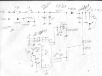
See this scratch for a step up and, if you realize it's ok for you, I can send more information about them (in this case I needed only 17V, but it can handle much more. It was my first scratch for this circuit, but I can find the definitive one somewhere).
regards
It would be easier than make a transformer if you consider you will need only two inductors. Depending on the power and frequencies needed you will find commercial units.
See this scratch for a step up and, if you realize it's ok for you, I can send more information about them (in this case I needed only 17V, but it can handle much more. It was my first scratch for this circuit, but I can find the definitive one somewhere).
regards
Attachments
I don't wan't to use a big, heavy transformer or a complex switcher, and I like the fact that each switching device wouldn't have to handle much power. That is the motivation for this design.
I Thought it up on my own, but, as one might guess, I got the idea from a Marx generator, which is a high voltage multiplier used to produce artificial lightning. The only difference is that in a Marx generator, S1-S16 are high value resistors, and S17-S26 are spark gaps.
Anyway, it should be obvious how the switching devices in my circuit would be biased. Right now, my plan is that they would all be N-channel MOSFETs so I wouldn't have to deal with thermal runaway. Drains (or collectors, if I use BJTs) would go to the positive terminal of the battery or capacitors. I don't believe there would be any problems, as long as they are all rated for the total output voltage of the circuit.
There are still some things that I'm wondering about the circuit. How do I figure out what the switching freq. and capacitances would need to be? Are there any other problems with this system that I haven't caught yet?
I must say, however, that there is something neat about my design, not just because I thought of it, but because it is effectively a DC transformer. It can step up or down just by turning it around, like a transformer, has almost all the versitility of a transformer (as long as it has a proper power supply for a control circuit to do the switching), and even has isolation.
But I would just as soon use any method for building car amps, as long as it's easy, and lightweight.
But I would just as soon use any method for building car amps, as long as it's easy, and lightweight.
Kilowatt,
I was looking for some reliable and simple sources to help you to build the power supplies.
The boost type can reach 400W in theory. There are drawbacks and some questions about stability, but I think you can start with this references to build a prototype for less power and increase it if the things work well.
The first is the National Power IC's Databook - at the LM3524D IC section. Maybe on the Internet you would find it too. But the book is very cheap. There are equations and information about the two types of power supplies (step up and voltage inverter).
The second is a Martin Brown's book (ISBN 0-12-137030-5) called Pratical Switching Power Supply Design, where you find more information about MOSFET selection, currents and waveforms for these types of power supplies.
I can, of course, help you with the matter if you want (and if my knowledgment about SMPS allows...).
Regards,
Kilowatt,
Your idea is a charge pump. It's used in various ICs like the MAX232 interface, which as a side effect of its interface requirements generates +/-10V from a +5V supply.
Check the Maxim website for some of these ICs. I don't think they scale up to the level you're wanting, but I don't know why. I suspect it might have to do with the peak charging current and losses in the capacitors, but I've never really looked into it. It seems to me the highest I've seen was around 200 mA output.
- Status
- This old topic is closed. If you want to reopen this topic, contact a moderator using the "Report Post" button.
- Home
- Amplifiers
- Solid State
- Non-traditional switching supply