For an audio amplifier, you do not especially need a low drop transformer.I was wondering how to work out the zener setting for the regulator (minimum required voltage drop), based on predicted voltage drop from rectifier (KBPC2506 per each secondary) and documented voltage drop from transformer and the possibility of a 4 ohm speaker load (or the similar load of a rather difficult 8 ohm speaker).
My 400va transformer datasheet gives these figures.
No load: 26v (secondaries in parallel)
7a load: 25.5v (secondaries in parallel)
10a load: 25v (secondaries in parallel)
17a load: 24v (secondaries in parallel)
Some people would choose a half price transformer, like this 200va:
No load: 28v (secondaries in parallel)
6a load: 26v (secondaries in parallel)
9a load: 25.5v (secondaries in parallel)
Apparently, if you buy a transformer based on lowest voltage drop figures, that results in a very huge transformer. It is 13cm across, 6cm tall and very heavy. I've listed two transformers in order to get 2 data points for extrapolation, so that you won't have to answer the same question for every transformer variety.
I'm assuming that the answer for monobloc (running with the 200va example above) is something like the ~6a pulldown figure (26v), multiply by 1.45? for capacitor rectification, subtract 2.5 for margin and then the zener figure is (15+20) 35v? Correct?
I'm also assuming that a stereo amp (running with the 400va example above) is going to be using 33v zeners at the regulator boards?
Gratuitous transformer overdo photo:")
Predicting the actual output voltage when the transformer is used in its actual circuit is pretty difficult, because of the peak rectification.
Anyway, you can be sure of one thing, the DC output will never exceed the (Vac*1.41)-1.5, and depending on the transformer, it could be significantly lower.
With your figures, under no load that would be ~=35V, falling to 30.5V or less peak under heavy load.
But you cannot use the peak voltage, the regulator must be able to regulate down to the minima of the voltage.
If you have 10% ripple, that would be 27V, and you need a regulating margin of 3V, that brings you to 24V. See why I advise against regulators?
you would have to insert a volume control in the very low level circuitry, and that would be difficult to achieve cleanly and without adding noise.
This was going to be my next question, if it was such an easy operation like adding somewhere a network consisting a couple of resistors, capacitors and small transistors.
Edit: I'm building a prototype of last revision of CFP PCB at this time. I will share files after accomplishment.
Last edited:
That becomes a preamplifier then, which is the sensible solution:a network consisting a couple of resistors, capacitors and small transistors.
Discrete design: 2-transistor RIAA preamp
. . . no load that would be ~=35V, falling to 30.5V or less peak under heavy load. But you cannot use the peak voltage, the regulator must be able to regulate down to the minima of the voltage. If you have 10% ripple, that would be 27V, and you need a regulating margin of 3V, that brings you to 24V. See why I advise against regulators?
Good example! Thanks!!!!
So, I probably need an unreg supply with (40+7) 47vdc available under heaviest load conditions, in order to get 40vdc regulated?
Or did I need (40+27%) 51vdc unreg available under heaviest load conditions, in order to get 40vdc regulated?
Good example! Thanks!!!!
So, I probably need an unreg supply with (40+7) 47vdc available under heaviest load conditions, in order to get 40vdc regulated?
Or did I need (40+27%) 51vdc unreg available under heaviest load conditions, in order to get 40vdc regulated?
Daniel, did you ever mind balanced configuration? I think something like this would fit your approach better. Though if you are not planning to use balanced conf with this power level already.
I was not kidding earlier, posting the picture of the battery.
Just trickle charge a stack of two or three glass mat batteries
per rail. Disconnect charger whenever you demand zero ripple.
You want the absolute quietest supply? Battery would be it.
Put a 13V zener across each battery to prevent overcharge.
AGM should not be charged 14V, like a vented car battery.
They might last a decade if you never charge past 12.6V.
Charging is rather slow at that rate, but you got the time...
Impress your friends with the sheer absurd weight of it all.
Last edited:
You can compute backwards, from the target voltage.Good example! Thanks!!!!
So, I probably need an unreg supply with (40+7) 47vdc available under heaviest load conditions, in order to get 40vdc regulated?
Or did I need (40+27%) 51vdc unreg available under heaviest load conditions, in order to get 40vdc regulated?
For 40V, you need 43V min. at the input, add 10% ripple, that is 47.3V, 2V diodes drop = 49.3V, divide by 1.41, you get 35V AC nominal voltage.
If you want to factor in the mains variation, yo need to add a further 5 or 10%.
I hadn't considered balanced input since my sources are all single rail. Are there still advantages to balanced input?Daniel, did you ever mind balanced configuration?
The floor standing radio plans have changed over to bi-amp.I was not kidding earlier, posting the picture of the battery. Just trickle charge a stack of two or three glass mat batteries per rail. Disconnect charger whenever you demand zero ripple. You want the absolute quietest supply? Battery would be it. Put a 13V zener across each battery to prevent overcharge. AGM should not be charged 14V, like a vented car battery. They might last a decade if you never charge past 12.6V. Charging is rather slow at that rate, but you got the time...
Impress your friends with the sheer absurd weight of it all.
The midbass, midrange, tweeter amplifier can run either batteries or regs--Sometimes the needed runtime is 19 hours, so probably regs.
With such a low crossover point, bass-only amplifiers run fine on unregulated power. Perhaps the bass-only amplifiers can now use parallel output devices? Maybe?
I hadn't considered balanced input since my sources are all single rail. Are there still advantages to balanced input?
With a a driver like DRV134, you can get balanced signal with an unbalanced source. Very easy setup but requires extra small symmetrical rails from 5V to 15V for supply.
Since that you have to build 2 amps per channel, then load will be shared by each amp then quadruple total output power. In your case 4 ohms will be shared as 2 ohms per amp, then total ~400 watts per channel with 32V rails.
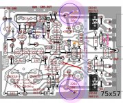
CFP PCB status
I have finished CFP PCB with bc546/bc556's which differs from my very first CFP build with bc550/bc560's. I faced with a dancing dc-offset problem. Then I have to do some more to fix this issue.
I have tested MJ15003's and they are OK. Good devices.
I have finished CFP PCB with bc546/bc556's which differs from my very first CFP build with bc550/bc560's. I faced with a dancing dc-offset problem. Then I have to do some more to fix this issue.
Any opinions on MJ15003's in this circuit?
I have tested MJ15003's and they are OK. Good devices.
I have finished CFP PCB with bc546/bc556's which differs from my very first CFP build with bc550/bc560's. I faced with a dancing dc-offset problem. Then I have to do some more to fix this issue.
What happens when R21 is too high or too low? I do no know. Perhaps too low causes too hot, but too high inspires a spurious noise which "may" be accompanied by an offset fluctuation?
What happens when D8+D9 is too high or too low? It is likely that too low would be a slightly warmer driver but I do not know what happens if too high. I think that D8+D9 should represent "1/2 the total voltage span" "in fully loaded condition" and that way the value is never too high.
What happens when C3 is too small and/or C10 is too large? Well, in that case, the largest signals, which are subharmonic, can be tall enough to switch on (blink on) D10, D11, creating, temporarily either a DC coupled or mixed coupled amplifier, but only for the duration of the extra low bass beat and only if there is enough input voltage to do it. The offset would dance to the bass beat. A big enough C3 keeps D10, D11 off.
Constraining the input:
Computer sources (any digital single rail source) can output a lot of crazy, so it is probably good to restrain that a bit. Did you try my back to back (inversely series) zener device put parallel to R20? That is a general purpose overload blocker that "blocks crazy" since it is capacitive to block RF and also you can set its clipper (Zener+0.7) to limit overload at the input.
I used 3.6v zeners, but I guess that larger value zeners, like 5.1v will work. The zener value is to abruptly shorten all unexpectedly overlarge signals that you didn't want to amplify. If the zener value is too small, that would sound exactly like clipping but if it is unnecessarily too large the effectiveness is diminished. The standard overload blocker is enough to stop most oddities, but you have to decide how much input voltage is useful and get zeners barely bigger than desired signal. The photo below (it is 5.1v+0.7v) is only an example, so use a value suited to your source device(s).
Attachments
Last edited:
What happens when R21 is too high or too low....
On first run offset falls down to 1mV Ievel and begins to raise up to many volts. I checked all semiconductors and some resistors including R21. It is not marginal, 46K.. D8+D9 is a single 1W 30V zener.. I used carbon film resistors everywhere excluding 330R, 1R, 0R47 which are metal oxide. I altered input transistors also.. Actually I don't want to struggle much more with this build because I have altered the pcb again and I want to build that one from scratch.
I haven't tested your overload blocker..there is no reason to not to give a try. Since that it is a very easy and specific addition, it may best to solder under the pcb.
Any comments welcome.
Attachments
Last edited:
Thanks man!Daniel have you tested your overload circuit as there is nothing to limit the current once the Zenner conducts. You may get away with this as it is AC coupled but if you have a really big AC input it will destroy the Zenners.
Andrew
Are you thinkin' what I'm thinkin'? This zener device might be a useful softer clip limiter if put series to (intercepting) the ground side leg of a voltage divider. Then, the + leg of the voltage divider also serves up some useful current limiting. Awesome! The sources will withstand 62R/62R+D+D (regardless of zener value). But, I cannot guess optimum for the 2 resistor values. What values should I use?
BC547 Q12 or Q11 will fail. VCEO = 45v and if 61v, it would go all unexpected.Any comments welcome.
BC546 Q12, Q11 works up to 65v, aka pair of 32v rails; however, a power surge will knock one out.
2SC2240 Q12, Q11 could stand up to whatever voltage and still work as a transistor.
Miniature Circlophone?
I am curious to know of what resistor and other values may change to optimize BC639 for Q5, Q6 (esp lower heat) and what is the maximum permissible rail voltage without overheating the BC639?
P.S.
I spotted some cute little MJE3055 (to220) to use for a small scale Circlophone.
I am curious to know of what resistor and other values may change to optimize BC639 for Q5, Q6 (esp lower heat) and what is the maximum permissible rail voltage without overheating the BC639?
P.S.
I spotted some cute little MJE3055 (to220) to use for a small scale Circlophone.
Last edited:
- Home
- Amplifiers
- Solid State
- ♫♪ My little cheap Circlophone© ♫♪