The direct connection of C19 and C20 seems very heavy handed, to say the least.Hello all,
I just finished to draw the PCB for my variation of the Circlophone, the Jfet one.
Please find here attache a schematic, a PCB in .pdf format and a .zip format with the Cadsoft Eagle project files.
Hope you like it, and please let me know any errors, doubt or improvement I can add.
Ciao,
Giovanni
Were such large values required for stability? If it is actually the case, it is probably a symptom of something wrong elsewhere.
I cannot see how a decent SR can be achieved with such large values
The direct connection of C19 and C20 seems very heavy handed, to say the least.
Were such large values required for stability? If it is actually the case, it is probably a symptom of something wrong elsewhere.
I cannot see how a decent SR can be achieved with such large values
My mistake, I simply copied C18 for the package, and forgot to update the value.
Actually the schematic simulates fine with two 3.3pf capacitors (you can try it with from the attached .zip)...
It simulates even without any capacitor, but I preferred to provide space for the capacitors however.
hi bigun I have an article from ww world dec 1999 you might like to view. New Class AB power amp eliminating cross over distortion.
That's an amp by Wim de Jager, Erik van der Ven and Ed van Tuyl.
I like the schematics. PM for those interested by the full article.
Hello all,
Hello Giovanni,
D2 and D8 are power diodes with thicker legs. It seems you won't able to fit them to those holes. You could also consider MBR type TO-220 package diodes as an option.
Neat PCB layout btw.
Edit: R36 is unneeded. Total resistance at positive rail must be 1 ohm. But It is 0.5 ohm in your case. Negative rail current sensing resistor value is correct, which is 1||1=0.5 ohm.
Regards.
Last edited:
Hello,
Thank you all for the comments, and thank you so much, Forr, for your kindness.
I reviewed the schematic, replacing the wrong components values.
@Elvee:
@Terranigma
I think I could fit the diodes, but I'll give a try to TO220 two legs diodes, it is a good idea.
I just revisited it, I think it is more clear now.
I wanted to leave two resistors per rail, just to be sure I can fit right values... Now I have modified the schematic with the right values.
There's no problem in installing only one resistor per rail, with the right value.
I've also changed the CCS back to Elvee's one, it is much simpler, and the BJT is way more easy to find; moreover, I can't find my 2SK246 box in anywhere (I know I have them, but I don't know where)... so switched back to BJT.
EDIT: If you want to open the PCB project with Eagle Cadsoft, remember you have to execute a "ratsnest" (sic) command to show the added copper polygons.
Ciao,
Giovanni
Thank you all for the comments, and thank you so much, Forr, for your kindness.
I reviewed the schematic, replacing the wrong components values.
@Elvee:
Now capacitors value are correct, thank you.The direct connection of C19 and C20 seems very heavy handed, to say the least.
Were such large values required for stability? If it is actually the case, it is probably a symptom of something wrong elsewhere.
I cannot see how a decent SR can be achieved with such large values
@Terranigma
D2 and D8 are power diodes with thicker legs. It seems you won't able to fit them to those holes. You could also consider MBR type TO-220 package diodes as an option.
I think I could fit the diodes, but I'll give a try to TO220 two legs diodes, it is a good idea.
Thank you very much.Neat PCB layout btw.
I just revisited it, I think it is more clear now.
Still another wrong value.R36 is unneeded. Total resistance at positive rail must be 1 ohm. But It is 0.5 ohm in your case. Negative rail current sensing resistor value is correct, which is 1||1=0.5 ohm.
I wanted to leave two resistors per rail, just to be sure I can fit right values... Now I have modified the schematic with the right values.
There's no problem in installing only one resistor per rail, with the right value.
I've also changed the CCS back to Elvee's one, it is much simpler, and the BJT is way more easy to find; moreover, I can't find my 2SK246 box in anywhere (I know I have them, but I don't know where)... so switched back to BJT.
EDIT: If you want to open the PCB project with Eagle Cadsoft, remember you have to execute a "ratsnest" (sic) command to show the added copper polygons.
Ciao,
Giovanni
Attachments
Last edited:
J74 input FET
If you are going to use the J74 FET as input, you could step-up the input impedance. Then you could get rid off the (4u7) lytic input capacitor and use a quality film capacitor. Or you could use two 2u2 film capacitors in parallel in case you stay with the 10K input.
have fun!
If you are going to use the J74 FET as input, you could step-up the input impedance. Then you could get rid off the (4u7) lytic input capacitor and use a quality film capacitor. Or you could use two 2u2 film capacitors in parallel in case you stay with the 10K input.
have fun!
That's an amp by Wim de Jager, Erik van der Ven and Ed van Tuyl.I like the schematics. PM for those interested by the full article.
Hi, currently there were six persons interested.
Some of them may have received the PDF file with page 983 missing.
Just tell me, I'll send a new file with the correction.
Thanks for your interest for this design.
Hello all,
I'm proceeding with the amplifier, I preparred the PCBs, and I'm now populating them.
Unfortunately, I made a mistake: I used TO220 package for both drivers and VAS transistors, just to be sure (I was playing with the idea to use BD240 drivers); but I discovered today (I knew it, but forgot) that TO220 and TO126 have different pinouts (inverted)!
So, I can't install TO126 into provided pins.
I still can install TO126 VAS transistors, simply inverting their position, but I cannot easily swap drivers transistors, since they have to be installed onto the same heatsink where finals are installed...
So, is there any valid TO220 alternative for the drivers?
Are BD240 suitable? I know they are way too big, but I have them in stock.
Or, even worse, TIP42C?
At least, I discovered the problem before to power the amplifier and burn everything!
Thank you in advance.
Ciao,
Giovanni
Attachments
Hello all,
I'm proceeding with the amplifier, I preparred the PCBs, and I'm now populating them.
Unfortunately, I made a mistake: I used TO220 package for both drivers and VAS transistors, just to be sure (I was playing with the idea to use BD240 drivers); but I discovered today (I knew it, but forgot) that TO220 and TO126 have different pinouts (inverted)!
So, I can't install TO126 into provided pins.
I still can install TO126 VAS transistors, simply inverting their position, but I cannot easily swap drivers transistors, since they have to be installed onto the same heatsink where finals are installed...
So, is there any valid TO220 alternative for the drivers?
Are BD240 suitable? I know they are way too big, but I have them in stock.
Or, even worse, TIP42C?
At least, I discovered the problem before to power the amplifier and burn everything!
Thank you in advance.
Ciao,
Giovanni
As what I'm understanding from your explanation is, you actually planned to use BD140 type transistors as drivers but you designed the pcb for BD240 thus you are asking any good drivers in TO220 package. If so, I can easily recommend you to use 2SA1930 because I have used it without any problem in the past. But I also see no reason to discard BD240B/C (B240 has 45V Vce which is problematic, Bd240A has 60V Vce so max 2*25V supplies) and TIP42C (100V Vce). They are fine as drivers as their Vce specs satisfy your PSU voltages.
Regards.
Hello terranigma,
I tried to develop the pcb to be "universal", so anyone interested could use it with the preferred schematic.
One can use the PCB with input BJTs or NJFET, VAS and driver transistors of his choice.
I tried to create a board that could accommodate TO220 or TO126 transistors, but I forgot that the two formats have different pinouts...
In fact you can, especially if your amplifier is not of huge power, which is your case: you can mount the plastic side against the heatsink, and use your insulating washer on the screw head side and conductive side of the TO126 (be sure to use a good quality, burr-free, wide flat washer between the screw head and the insulating washer)but I cannot easily swap drivers transistors, since they have to be installed onto the same heatsink where finals are installed...
If you can find brass hardware, it will be almost as good as the normal mounting method from a thermal point of view, otherwise use ordinary steel and try to avoid stainless steel.
That said, there will be no problem, even with stainless steel.
I sometimes deliberately use that mounting method, because it is more suitable in some cases
In fact you can, especially if your amplifier is not of huge power, which is your case: you can mount the plastic side against the heatsink, and use your insulating washer on the screw head side and conductive side of the TO126 (be sure to use a good quality, burr-free, wide flat washer between the screw head and the insulating washer)
If you can find brass hardware, it will be almost as good as the normal mounting method from a thermal point of view, otherwise use ordinary steel and try to avoid stainless steel.
That said, there will be no problem, even with stainless steel.
I sometimes deliberately use that mounting method, because it is more suitable in some cases
Hello,
Yes, I think I'll do that way; I already have BD140 and don't want to buy anything else...
I can also build two small heatsinks for the two drivers.
However, I have to remove the soldered drivers and rotate them...
Praise of circlophone ...
it was not so easy to get the proper drivers BD139/140 F but ok. I made two circlophones for an active shelf speaker. I do not really want to engage in speaker building but these had to match the wood of the furniture in my office so...no other choice. The sound was excellent in the bass/midrange and subjectively even better in the high range. The types of power transistors did not matter. But alas...the properly sized heatsink and transformer took up to much space , i tried then a single supply version with a dc step down converter for the tweeter amp which is already oversized at 20 watts output. But this did not sound really good. So alas i had to give up because the cabinet is quite expensive i did not want to add more cost making a smaller one. Or it did not fit in the shelf space . The final version has standard chip amps, not that bad, but they do not produce the fine sound quality of the circlophones. A bit like listening through a curtain, not clear something is wrong. I gave the circlophones to a friend.
it was not so easy to get the proper drivers BD139/140 F but ok. I made two circlophones for an active shelf speaker. I do not really want to engage in speaker building but these had to match the wood of the furniture in my office so...no other choice. The sound was excellent in the bass/midrange and subjectively even better in the high range. The types of power transistors did not matter. But alas...the properly sized heatsink and transformer took up to much space , i tried then a single supply version with a dc step down converter for the tweeter amp which is already oversized at 20 watts output. But this did not sound really good. So alas i had to give up because the cabinet is quite expensive i did not want to add more cost making a smaller one. Or it did not fit in the shelf space . The final version has standard chip amps, not that bad, but they do not produce the fine sound quality of the circlophones. A bit like listening through a curtain, not clear something is wrong. I gave the circlophones to a friend.
So alas i had to give up because the cabinet is quite expensive i did not want to add more cost making a smaller one. Or it did not fit in the shelf space . The final version has standard chip amps,
A pity: Terranigma also faced the same kind of dilemma and followed the same route because of dissipation, but in the end he went back to the C, IIRC.
Adaptive class A is mostly adaptive, but it has some of the demands of class A too, that's 3 or 4 times that of conventional AB, normally not too much of a problem, except when the design is constrained
Really a pity indeed.... especially because the circlos , provided the few sensitive parts are the proper ones, work perfectly on first power on. The compensation has some headroom to make it faster, but such did not yield audible differences. One could say "a truly musical amp". It mastered the hardest reality test, direct cut vinyl, quite well.
My Inverted Circlophone, by Piersma
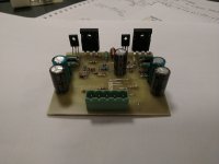
Here are some pictures of boards of my Inverted Circlophone (boards provided and assisted by Piersma). The amp has the signal input from the preamp section of a Harman Kardon HK1200 amp. The last boards image was taken during tests. I still have to provide adequate heat sinks and case for it, modify two outputs, make a higher voltage rating capacitor bank (63Vdc). The amp is being fed by 25Vdc with ~15,000uF per rail of 42Vdc Panasonic caps.
Sound is VERY GOOD from low end to high freqs! Thanks Elvee and thank you Piersma for all the assistance, tests and measurements.
Resistors are all metal film rated 0,6W and all the components used in my boards can be seen in the last silk screen pic with these marked in RED in substitution of originals. BOM (from Digikey) is available to those who are interested.
TESTS - the two "wired" outputs were just to take place in the pre drilled heat sink, and need a better one actually
SILK SCREEN WITH COMPONENTS IN MY CP MARKED IN RED
Here are some pictures of boards of my Inverted Circlophone (boards provided and assisted by Piersma). The amp has the signal input from the preamp section of a Harman Kardon HK1200 amp. The last boards image was taken during tests. I still have to provide adequate heat sinks and case for it, modify two outputs, make a higher voltage rating capacitor bank (63Vdc). The amp is being fed by 25Vdc with ~15,000uF per rail of 42Vdc Panasonic caps.
Sound is VERY GOOD from low end to high freqs! Thanks Elvee and thank you Piersma for all the assistance, tests and measurements.
Resistors are all metal film rated 0,6W and all the components used in my boards can be seen in the last silk screen pic with these marked in RED in substitution of originals. BOM (from Digikey) is available to those who are interested.
An externally hosted image should be here but it was not working when we last tested it.
An externally hosted image should be here but it was not working when we last tested it.
An externally hosted image should be here but it was not working when we last tested it.
An externally hosted image should be here but it was not working when we last tested it.
TESTS - the two "wired" outputs were just to take place in the pre drilled heat sink, and need a better one actually
An externally hosted image should be here but it was not working when we last tested it.
SILK SCREEN WITH COMPONENTS IN MY CP MARKED IN RED
An externally hosted image should be here but it was not working when we last tested it.
Last edited:

Inverted J-Fet Circlophone boards
I am in the process of ordering the final production run of the (inverted J-Fet) Circlophone boards. Boards as presented in post #1477. Schematic post # 1212.
Over time I have had several private inquiries for Circlophone PCB's and at this moment there is another request for boards.
If you are interested please put your name on the list in this threat. This will be the last Circlophone boards I intend to order.
This list will be open till 28 of February.
best regards,
Piersma
- Home
- Amplifiers
- Solid State
- ♫♪ My little cheap Circlophone© ♫♪