^Thanks!, I have etched the board i will be populating it soon...") The objective is to create another compact board yet avoiding vertical mounting (especially the resistors).
The objective is to create another compact board yet avoiding vertical mounting (especially the resistors).
I have found a Class D type heat sink (aluminum bar) which perfectly matches the space provided for it for the VAS. I just hope this new design will work smoothly...
Regards!
The objective is to create another compact board yet avoiding vertical mounting (especially the resistors).I have found a Class D type heat sink (aluminum bar) which perfectly matches the space provided for it for the VAS. I just hope this new design will work smoothly...
Regards!
Thanks Elvee and abetir!
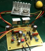
abetir - I etched and built your board up, layout is great and works perfectly! I built the board on very minimal budget with what I could find on ebay Q12/Q13 are 2SC2240, Q5/Q6 are 2SC3421, D3/D4 are 10SQ045. One minor issue is that the BD140s are getting very hot and I suspect they are fakes. The heatsinking in the pic is just for testing.
Cheers, Dan.
abetir - I etched and built your board up, layout is great and works perfectly! I built the board on very minimal budget with what I could find on ebay Q12/Q13 are 2SC2240, Q5/Q6 are 2SC3421, D3/D4 are 10SQ045. One minor issue is that the BD140s are getting very hot and I suspect they are fakes
. The heatsinking in the pic is just for testing.Cheers, Dan.
Attachments
Excellent Dan!
..pretty clean build from the looks of it the BD140s could have been fakes (not so sure though ), original phillips are gray in color and I guess they are becoming very hard to obtain. I see you are using metal cans for the output, also put a heatsink on VAS any small type (or DIY) should fit nicely on the space provided. I'm glad it works!
Just be sure to follow the power chart table.
Thank you Dan.
..pretty clean build
from the looks of it the BD140s could have been fakes (not so sure though ), original phillips are gray in color and I guess they are becoming very hard to obtain. I see you are using metal cans for the output, also put a heatsink on VAS any small type (or DIY) should fit nicely on the space provided. I'm glad it works!Just be sure to follow the power chart table.
Thank you Dan.
It is normal the BD140 become hot, they dissipate a significant quiescent power, and that is true whether they are fake or not.One minor issue is that the BD140s are getting very hot and I suspect they are fakes.
Yours are certainly not original Philips, but that doesn't mean they are actually fakes: they could be from Telefunken, Siemens, ST, Motorola, etc
Well chuffed...
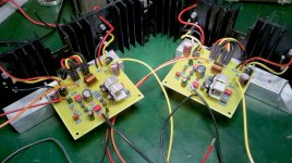
abtir, Elvee - I think you were right about my original ST BD140s being genuine (I was suspicious of the very neat printing and shiny legs, in addition to the fact they were from China and very cheap). I ended up replacing them for NOS scruffy grey Philips ones I found anyway. Thought you might like to see my finished boards, the BD140s are bolted to aluminium box section and the boards stand off. Still need boxing up (each assembly is one side!) but I'm listening to them now and I'm very happy
abtir, Elvee - I think you were right about my original ST BD140s being genuine (I was suspicious of the very neat printing and shiny legs, in addition to the fact they were from China and very cheap
). I ended up replacing them for NOS scruffy grey Philips ones I found anyway. Thought you might like to see my finished boards, the BD140s are bolted to aluminium box section and the boards stand off. Still need boxing up (each assembly is one side!) but I'm listening to them now and I'm very happy It is normal the BD140 become hot, they dissipate a significant quiescent power, and that is true whether they are fake or not.
Yours are certainly not original Philips, but that doesn't mean they are actually fakes: they could be from Telefunken, Siemens, ST, Motorola, etc
Attachments

Here are some fresh news from the front:
Member Piersma has developped his own "deluxe" version of the Circlophone: it uses a cascoded jFET input stage amongst other improvements, and offers better overall performances at the cost of a manageable increase in complexity.
It still retains the basic Circlophone principles, meaning optimal sound quality without adjustments or thermal problems.
Sjerko has kindly sent me two boards for evaluation, and after some minor adjustments of the compensations, they work beautifully.
This version is therefore ready to be built and tested by others.
I'll let Sjerko himself present his work and material.
latest Circlophone incarnation
Inverted JFET Circlophone,
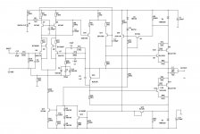
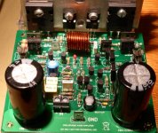
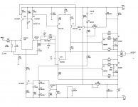
With reference to post number 331 of this threat, this is final version of the “inverted JFET Circlophone”.
Real life implementation of the attached schematic is shown in the picture.
The design is fully tested and approved by the designer of the original Circlophone, Elvee.
Highlights of this version:
Scalable outputpower, rails up to 50V
JFET input, (virtual) absence of gate/base modulation
Improved step response of the CFP configuration
Reduced phase splitter dissipation
Original Circlophone features:
No (very low…) cross-over distortion, semi class A
No need for thermal tracking the output devices
Idle current 200 mA, Gain : 28 dB
Inverted JFET Circlophone,
With reference to post number 331 of this threat, this is final version of the “inverted JFET Circlophone”.
Real life implementation of the attached schematic is shown in the picture.
The design is fully tested and approved by the designer of the original Circlophone, Elvee.
Highlights of this version:
Scalable outputpower, rails up to 50V
JFET input, (virtual) absence of gate/base modulation
Improved step response of the CFP configuration
Reduced phase splitter dissipation
Original Circlophone features:
No (very low…) cross-over distortion, semi class A
No need for thermal tracking the output devices
Idle current 200 mA, Gain : 28 dB
Attachments
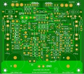
Board Files
Inverted Circlphone PCB files.
Note: Zobel (R=5E6, C=47nF) is optional !
have fun!
Inverted Circlphone PCB files.
Note: Zobel (R=5E6, C=47nF) is optional !
have fun!
Attachments
Last edited:
I'm working on another MOSFET version for a friend. It is based on HEXFET outputs and keantoken's buffered input stage arrangement. I made a simulation according to my devices on the shelf. Everything seem fine with the models that I found at various sources and customized compensation values. But I have no clue about amp's predicted stability margin. Any suggestion appreciated in this regard.
Thanks.
Thanks.
Attachments
I'm surprised anyone remembers that.
It looks like your FETs are running at 7.5A bias. You forgot R22 in the schematic above your post.
EDIT: Here, an attached schematic with R22 and the AC analysis fixed. A bit peaky. The compensation could stand some tuning for sure, but it doesn't seem to be blowing up yet.
It looks like your FETs are running at 7.5A bias. You forgot R22 in the schematic above your post.
EDIT: Here, an attached schematic with R22 and the AC analysis fixed. A bit peaky. The compensation could stand some tuning for sure, but it doesn't seem to be blowing up yet.
Attachments
Last edited:
I'm surprised anyone remembers that.
It looks like your FETs are running at 7.5A bias. You forgot R22 in the schematic above your post.
EDIT: Here, an attached schematic with R22 and the AC analysis fixed. A bit peaky. The compensation could stand some tuning for sure, but it doesn't seem to be blowing up yet.
Thanks for input. I thought that resistor (R14 in original schematic) is going to be superfluous if I use CCS in place of R21, as what I did in schematic.
I'm working on another possible compensation values now.
Last edited:
- Home
- Amplifiers
- Solid State
- ♫♪ My little cheap Circlophone© ♫♪