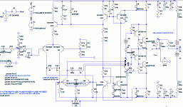
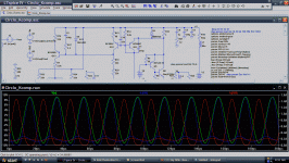
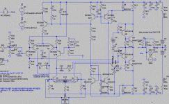
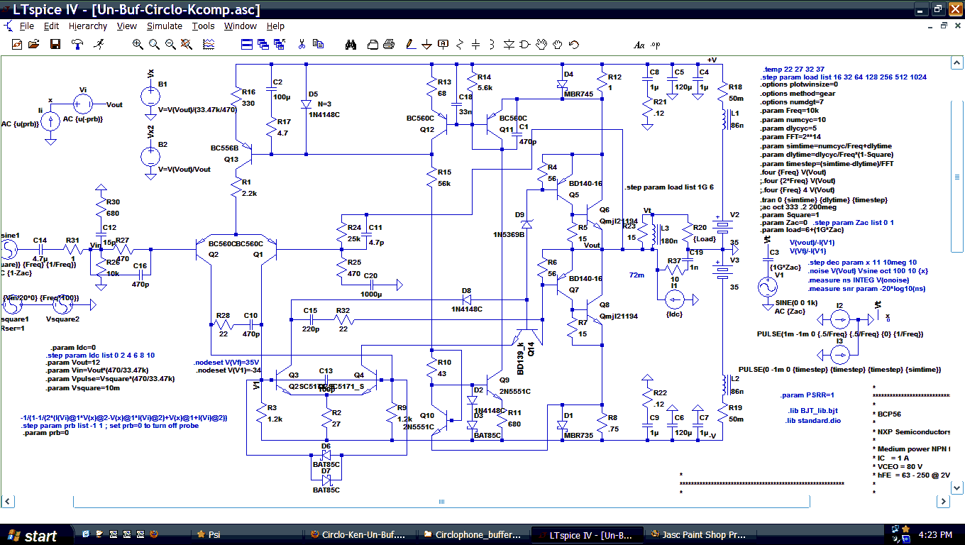
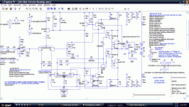
The drivers in post 998 are Philips BD140, but many drivers could be used for those results, since it isn't touchy about drivers.
However, it is very touchy about VAS components, and thus if 2SC5171 is exchanged for a substitute then the function would be less pleasant than expected. The problem is the capacitor parallel with the feedback resistor. Not only is tuning that in harmony with the vas compensation giving the excellent performance but it is also an Achilles heel. Some other and more tolerant way needs to be found or else there would be a schematic per each different vas device and per each different voltage. For example a variety of 5 transformers and 5 transistors requires 25 different schematics. . . because the vas compensation has tight tolerances and will neither successfully nor automatically adapt to differences. Ideas?
However, it is very touchy about VAS components, and thus if 2SC5171 is exchanged for a substitute then the function would be less pleasant than expected. The problem is the capacitor parallel with the feedback resistor. Not only is tuning that in harmony with the vas compensation giving the excellent performance but it is also an Achilles heel. Some other and more tolerant way needs to be found or else there would be a schematic per each different vas device and per each different voltage. For example a variety of 5 transformers and 5 transistors requires 25 different schematics. . . because the vas compensation has tight tolerances and will neither successfully nor automatically adapt to differences. Ideas?
VAS??? How can we speak of VAS in normal terms?
Modulated into Class B from beginning to end, you
have two very different VAS in a game of ping-pong.
The transistor that is shut off or held at low constant
current is not amplifying anything by comparison to
the other half which is active.
----
I see you have recently added Q16 to make both
halves of the cycle more similar. When did this
new part first appear, and why was it not worthy
of previous mention? It cuts severely into your
negative swing's headroom, so its not pure gravy.
Why bother at all with V6 + D8? If Q16 exists,
these should be mated with the same.
Last edited:
D8 is to keep the simulator from determining an operating point where V6 is pushing current the wrong way through the driver. It is just for the simulator.
I like your idea to cascode Q4 with the top of D8 as a reference.
AFAIK the VAS is in class A, except when overdriven or when being severely messed with by the servo loop. Furthermore, the servo loop itself ensures that the VAS, just like the output stage, has that non-switching characteristic. Furthermore, the VAS is certainly balanced, or currents of the outputs wouldn't be balanced or controlled so well, which they are.
In simulation a single 500pF cap across the bases of the VAS works well to iron out differences, ensuring a baseline of slowness. This modification should make me and Dan's variant more tolerant of different VAS devices.
Elvee, I know you've probably been there done that, but I value your input. As for instability... I haven't built it so I don't know what I'm missing... But I've been there with my current amp, so I think I have an idea. My experience is that there is probably a way to get the amp to work like in simulation, assuming the models aren't terrible and the real life devices aren't counterfeit.
Its ping-pong alright. One output transistor under control
of the differential feedback, The other under control of the
common mode feedback. Then roles reverse... And this
goes all the way back up the chain to the modulated tail.
Things only get complicated if the common feedback is
slower than the differential. If it were not quick enough
to hold the roles as separate. And during the crossing.
When we slug a VAS that affects both loops, are we then
shooting ourselves in the foot by enforcing a mixer in the
critical part of the Bodes where both rolloffs will occur?
I am not saying mixing makes unstable. I am saying the
mix makes analysis a nightmare. Becoming manageable
only if you break the problem into chunks that don't defy
traditional Bode analysis. As Bode assumes there will be
only one global loop, and it will be open. But ours must
properly handle the open differential mode with common
mode loop is closed, and therefore...
Last edited:
The servo is pretty slow. At frequencies that matter for compensation, the VAS is operating pretty much without any common-mode augmentation.
The 500p cap actually does not slow it down that much. Remember that low values of miller capacitance matter because they are multiplied by the voltage gain of the stage. This does not happen to emitter capacitance.
The 500p cap actually does not slow it down that much. Remember that low values of miller capacitance matter because they are multiplied by the voltage gain of the stage. This does not happen to emitter capacitance.
It might also be OK if the common mode is significantly
slower than differential. As this becomes class A at high
frequencies, and we know how to stabilize for that. But I
worry that way of compensation would invite meltdown
if an oscillation were to establish in spite of our efforts...
Faster, slower, either might be OK. But not the same.
Probably not anyway, I can't prove what I can't math.
And I cannot math this mixed Bode. I have tried.
If we approach the problem by slugging something
that affects both loops, we risk making both rolloffs
occur near the same corner. Full tentacled madness....
You want the common mode to dumb down to classA
somewhere above audio. and then much further above,
roll the differential? I suppose that is not so confusing...
What happens with a clipped audio signal that has a
high frequency component in the class A zone?
Last edited:
I'm pretty sure the VAS will still saturate before the LTP does. Remember that Elvee's versions have a lot more across the VAS bases, 1.5nF as I remember. Albeit with some series resistance, but the critical difference is that in that version the LTP would have saturated before the VAS. So I don't think this version would have any problems that Elvee's didn't have, in fact it may be better.
I found that the static and low frequency aspects of the Circlophone are very accurately modelled by the sim.Elvee, I know you've probably been there done that, but I value your input. As for instability... I haven't built it so I don't know what I'm missing... But I've been there with my current amp, so I think I have an idea. My experience is that there is probably a way to get the amp to work like in simulation, assuming the models aren't terrible and the real life devices aren't counterfeit.
For the dynamic aspects, it is a different story and there are discrepancies.
Some are positive, like the slew rates, power bandwidth and transient cleanliness as shown in the oscillograms better than the sim, some negative, essentially stability, worse than the sim.
The stability in a Bode sim is a necessary condition for the physical stability, but it is not sufficient by itself.
My hypothesis is that the two loops interact, creating a sort of "modal oscillation".
This cannot be caught by a simple Bode analysis, where you look essentially at the result of one stimulus on one loop at a time.
The transient analysis should be more accurate in this respect, and it sometimes is: making a simulation with very small time steps, like 1ns can help uncover some issues. But some discrepancies remain.
Maybe the models, maybe the physical layout, or some other unknown effect.
When oscillations occur, they are generally rather high in frequency, several MHz, and low in amplitude, less than 1Vpp thus pretty harmless and non-destructive.
So, it is perfectly feasible and safe to experiment and test various compensation schemes, practically without risk (not on a real speaker though).
Amongst other things, I found the lead resistor in series with compensation capacitors was practically unavoidable.
But maybe I was stuck on the wrong track and missed something. That kind of thing can happen when you are involved too deeply for too long in something, which is why I welcome the look of outsiders.
I made a quick test on two Circlophone builds I had handy: one is a completely unaltered version, with TIP3055 as OP, the other is based on BD249C.
I simply shorted R23:
On the plain vanilla C, it resulted in downright oscillations on the positive half cycles, on the BD249 one, nothing was visible.
This means that with somewhat better output devices, the margin is wider, but it doesn't mean it is sufficient for practical use.
At the time, I made my homework and made stress tests under many marginal conditions, with many semi's, etc, and came to the conclusion that the values published were near optimum. Or at least a local optimum. If a completely different compensation strategy was adopted, things might be different, but if the original scheme is retained, series resistors are probably necessary.
I know that it doesn't quite square with sim results, but in the end it is the physical circuit that has to be made to work, not the sim.
Un Buffered?
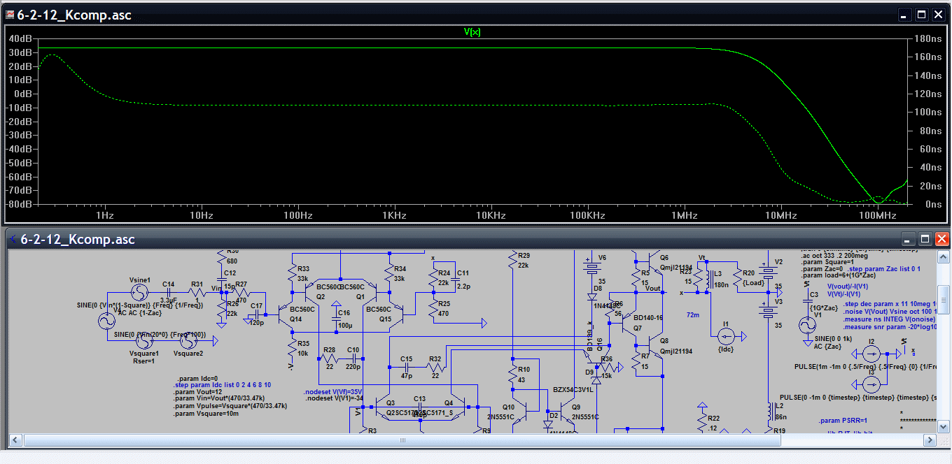
Apparently, that buffer really is an upgrade. For comparison, here it is without the buffer. This time it is at 2.5MHz and 0.002215% THD. Not shown is the harmonic effects of the output device currents being fairly jagged on this version as the sensor is not nearly as well behaved on this un-buffered version. There's not actually any sticking, but it is just not quite as level. Even so, it looked worthy of checking out the differences between the two versions (with and without the buffer). The compensation differences are especially interesting. It seems that either you have a buffer or you have double the compensation efforts (see attachment).
Apparently, that buffer really is an upgrade. For comparison, here it is without the buffer. This time it is at 2.5MHz and 0.002215% THD. Not shown is the harmonic effects of the output device currents being fairly jagged on this version as the sensor is not nearly as well behaved on this un-buffered version. There's not actually any sticking, but it is just not quite as level. Even so, it looked worthy of checking out the differences between the two versions (with and without the buffer). The compensation differences are especially interesting. It seems that either you have a buffer or you have double the compensation efforts (see attachment).
Attachments
Last edited:
0.000033%THD buffered Circlophone?
0.000033%THD@1kHz
0.000077%THD@10kHz
0.000712%THD@50kHz (shown)
Top speed on that one is 1.5MHz if you want strictly phase linear. It was simulated with the load engaged for more realistic results (for example if I took off the buffer, then the passive component values will look very much like post 1). The fantastic THD figures are because of unusual manipulation of the sensor values (see attachment), Q16 which cuts THD in half anyway, and the 2x better tolerances (easier to comp) seen when using the buffer. I was attempting higher efficiency, but this looks unusual and I do not know how to interpret the results. Help?
Attachments
Ah, practicality issues.
1
I read only one of the THD graps. The other says 0.0022%.
2
And R17 could go to 10 ohms or even a bit more if necessary for practical concerns of having that resistor large enough to assure that C2+R17 doesn't act like a bad cap but instead really does perform as an RC for consistent behavior. The entire goal of the latest exercise has been to break free of too small R17 values, and finally we did.
Attachments
Last edited:
Bias at 700mA will get you low distortion, and this amp seems to like class A. However notice the bias point changes between loaded and non-loaded. For some reason loading pumps up the bias. This may have to do with your changes to the servo.
Also, dunno if you know this, in LTSpice, Tools->write bitmap to clipboard and then paste into MSPaint will give you an instant schematic with no need for cropping window borders. Too bad it doesn't work in Linux.
Also, dunno if you know this, in LTSpice, Tools->write bitmap to clipboard and then paste into MSPaint will give you an instant schematic with no need for cropping window borders. Too bad it doesn't work in Linux.
I don't know what Q14 brings/improve, but it is unusable outside simulations: it will cause premature clipping of the output.The simulator regards this circuit as 0.0013%THD. Although I show it without the buffer, adding the buffer is probably vital if one wants to support a much wider range of components. Without further ado, see the altered cascode.
Cascoding Ken's way (on the other leg) does bring benefits, but here I only see additional problems.
D9 has to be somewhere around 66V to prevent premature clipping. So it's a bit weird, and too much rail sag could cause VAS saturation. We could fix this and use fewer components by just cascoding Both halves of the VAS. For some reason that option never seemed attractive I take it, but now it looks like the best way. It would also allow us to use smaller VAS devices with better Vcesat characteristics; I'll bet we could get away with the BC550C or the BC327-40 there.
- Home
- Amplifiers
- Solid State
- ♫♪ My little cheap Circlophone© ♫♪
