A word about D6/D7: if the BATxx is not available, a possibility is to replace both diodes by fast 1A ones like BYD33, BYV26, UF4004, etc.Elvee told me that the reverse voltage spec isn't used since there's no reverse voltage employed at those locations. At D4/5, the 35v and 45v diodes are fine.
At D7, you could use BAT86 if you wanted a stronger part, but BAT85 will also do fine.
This combination will be equivalent to 1N4148+BAT85 (Do not use schottkies!!!)
In Philippines, you could find a plenty variety of good transistors out there.
That is correct after I have sampled the sonic quality of this amp, I may have to settle for D1047s....
") But I think I am in trouble...right now. I did Elvees and using the latest mods for the CFP, but after powering, D669s were getting too hot in a matter of seconds...
But I think I am in trouble...right now. I did Elvees and using the latest mods for the CFP, but after powering, D669s were getting too hot in a matter of seconds...
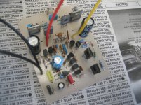
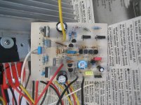
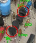
I am not so sure though if I did rightfully the mod for the omission of the offset trimmer. It was stated "apply 10k between point A and B". I decided to use a low +/-24vdc (pre-amp supply) just for a test. Near the 331pf (red cap) was the 470 ohms input resistor and in the image it was missing but I have corrected that now. I did a comparison with the component lay-out provided and it looks though that I did it correctly excepting the phase-splitter trannie as you can notice in the picture they were facing the other way because I used 2N5551. The TO-220 devices were MBR1045...but now I just can't seem to find what was amiss...

...guess I will be needing your help guys..

Attachments
At Q5, Q6? There's a high chance of fake Hitachi. You can review this photo to find out <link. . .D669s were getting too hot in a matter of seconds. . .
Do I see light gray colored drivers (Q9, Q11)? BD140 types max out at 40+40vdc rails.
The drivers do need a heatsink.
P.S.
There are some toshiba pairs that Elvee tested as working well for vas and driver--2sc5171, 2sa1930 and 2sc3421, 2sa1358
P.P.S.
With your 24+24vdc supply, did you also adapt R21, D8, D9?
Last edited:
R21=33k
D8, D9 = 12v 1w zeners
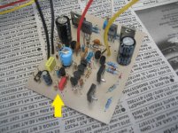
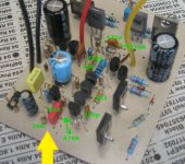
BD140 (gray) & D669a are fakes...but I am not so sure though, they look like made in the Philippines... In my place and in my experience, fake ones will work ok but of course they won't last. I've been utilizing them just for testing purposes only and when everything works fine I replaced them with the genuine ones. Genuine 2SC3421 is available here (expensive though costs 3x the local one). I have not installed the driver heatsink yet it was a quick test and the PSU was only around 0.5 ampere. Was the parts orientation correct?
D8, D9 = 12v 1w zeners
BD140 (gray) & D669a are fakes...but I am not so sure though, they look like made in the Philippines...
In my place and in my experience, fake ones will work ok but of course they won't last. I've been utilizing them just for testing purposes only and when everything works fine I replaced them with the genuine ones. Genuine 2SC3421 is available here (expensive though costs 3x the local one). I have not installed the driver heatsink yet it was a quick test and the PSU was only around 0.5 ampere. Was the parts orientation correct?A word about D6/D7: if the BATxx is not available, a possibility is to replace both diodes by fast 1A ones like BYD33, BYV26, UF4004, etc. This combination will be equivalent to 1N4148+BAT85 (Do not use schottkies!!!)
Can MR types be used for this?
R21=33k D8, D9 = 12v 1w zeners
BD140 (gray) & D669a are fakes...but I am not so sure though, they look like made in the Philippines...
I can't quite see the parts orientation. You'll just have to trace. Either that or go buy the trimmer.
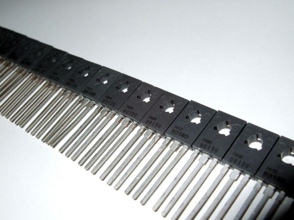
You might want to check your gray drivers to see if the leads are especially/unusually flexible because of soft copper inside the leads. Those might be the very rare (and desirable) Philips BD140, such as in this photo. <link
Very similar (from the link) the number was imprinted in black ink too, not the usual embedded pattern. The leads had this white powder coated flat finish and yes they are soft, easily bends when poked around...but they come cheap here so I figure they are imitation.
Early genuine Philips BD ones marked with ink and having soft legs (pure copper?) just like you mentioned. They have to used with heatsink bars on circuit.
If your heat observation related Q5/Q6 is really excessive, (I mean above 100 °C) you may be straight about for a possible issue. I used metal bodied genuine transistors as Q5/Q6 on my builds and I didn't notice any excessive heat dissipation from them with healthy builds. You have to be sure about they are genuine and you have to accept that plastic package transistors can't dissipate heat that much already.
Did you measure dc-offset and quiescence current? Circuit must waste 150-200mA without any load. Offset trimmer is not a critical part of circuit, you can omit it if you haven't any concern about precise offset. It has nothing to do with hundreds of milivolts of offset.
I attached an image with correct values with Elvee's latest experiments on CFP edition's compensation values.
Attachments
Last edited:
They're $10 apiece here and were discontinued in 1988. Maybe your vendor is unaware that the stock houses have eventually begun to run out.Very similar (from the link) the number was imprinted in black ink too, not the usual embedded pattern. The leads had this white powder coated flat finish and yes they are soft, easily bends when poked around...but they come cheap here so I figure they are imitation.
Anyway, if you have the gray Philips BD139, they're COB 6pf and the specs work for Q5, Q6 (a LOT better than fake hitachi exploding in about 10 minutes).
EDIT: The rating on the Philips BD139 says its going to need a heatsink, such as an inexpensive small to220 clip heatsink or the circle from the bottom of the beer can--anyway, about that much metal. They do also need thermal paste.
With the plastic case devices you'll need to get the heat out of them since they do all suffer from internal heat pooling because of their plastic cover.
Last edited:
Yes, practically any fast 1A diode will do.Can MR types be used for this?
terranigma/daniel,
It's weekend here, I'll get back on my build again and see what went wrong, thank you for the help.
terranigma, I can't do measurements because D669a heats up fast, in a few seconds I figure it will explode in smoke...
I will post updates again soon.
Sir Elvee, thank you for the updates UF series is much more easier to find here than BATs, I only found one local supplier that sells BAT85. Can 1N5818-22 qualify too?
Regards!
Last edited:
No. The 1n5818 datasheet says rectifier type schottky with a highly variable switch on point. If at D7, those will nuke your nards. And Elvee said:1N5818-22 qualify too?
1N5818-22 Rectifier schottky is not a signal type.. . .Do not use schottkies!!!. . .
1N5818-22 will misinform/misfire the sensor and that is not pleasant.
Last edited:
D7, ~1V illustration
1N4148 at D6, plus BAT86 at D7, sums up to 1V. <<-most durable example
1N4148 at D6, plus BAT85 at D7, sums up to 1V.
FR at D6, plus FR at D7, sums up to 1V (check datasheet graphs to confirm).
MR at D6, plus MR at D7, sums up to 1V (check datasheet graphs to confirm).
BY at D6, plus BY at D7, sums up to 1V (check datasheet graphs to confirm).
UF at D6, plus UF at D7, sums up to 1V (check datasheet graphs to confirm).
So, these examples are approximately 1V, at low current, in most temperature conditions.
P.S.
Conversely, 1n4148 at D6, plus 1N5819 may engage at 0.7v and cause a sensor misfire that would blow the output devices eventually, especially if the diodes are warm. And, 1N5819 at D6 plus 1N5819 at D7 will blow the output devices immediately. The 1n5819 and similar rectifier schottky have a highly variable switch on point that is very, very low voltage and thus not suitable for either D6 or D7, since random operation of the sensor wouldn't be useful.
Last edited:
CFP
It seems the first thing to do for going forward with the CFP. . . is to discover the maximum practical value for C5 (The standard schematic's "RF Filter" of 330p). Some people may experience rolled off/rounded treble with 3n3. I also tried 2n7, which was borderline. 2n2 looks decent. But, don't take my word for it--this needs tested because filtering depends on your source and your potentiometer. When using the 10k potentiometer, the input loss varies and that alters the filtering. SO, the first thing to do is try to find the biggest RF filter cap you can that won't dull your treble. Please help research this?
P.S.
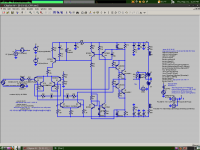
The following links will expire/change in time: It was possible to make Standard Circlophone and visually matching CFP Circlophone schematics, and, caution, this CFP schematic is possibly not ready for prime time (the values are probably not right)--It needs proofread, simmed, checked out. Help?
It seems the first thing to do for going forward with the CFP. . . is to discover the maximum practical value for C5 (The standard schematic's "RF Filter" of 330p). Some people may experience rolled off/rounded treble with 3n3. I also tried 2n7, which was borderline. 2n2 looks decent. But, don't take my word for it--this needs tested because filtering depends on your source and your potentiometer. When using the 10k potentiometer, the input loss varies and that alters the filtering. SO, the first thing to do is try to find the biggest RF filter cap you can that won't dull your treble. Please help research this?
P.S.
The following links will expire/change in time: It was possible to make Standard Circlophone and visually matching CFP Circlophone schematics, and, caution, this CFP schematic is possibly not ready for prime time (the values are probably not right)--It needs proofread, simmed, checked out. Help?
Last edited:
You can also keep the original 330p and increase R19 (on your schematic) to 4.7K.It seems the first thing to do for going forward with the CFP. . . is to discover the maximum practical value for C5 (The standard schematic's "RF Filter" of 330p). Some people may experience rolled off/rounded treble with 3n3. I also tried 2n7, which was borderline. 2n2 looks decent. But, don't take my word for it--this needs tested because filtering depends on your source and your potentiometer. When using the 10k potentiometer, the input loss varies and that alters the filtering. SO, the first thing to do is try to find the biggest RF filter cap you can that won't dull your treble. Please help research this?
Some corrections:The impedance is high enough to allow for it without inconvenient.
P.S.
The following links will expire/change in time: It was possible to make Standard Circlophone and visually matching CFP Circlophone schematics, and, caution, this CFP schematic is possibly not ready for prime time (the values are probably not right)--It needs proofread, simmed, checked out. Help?
C6=120p
R23=1K8
R2=47
C4=3p3
C2=390p
C12=270p
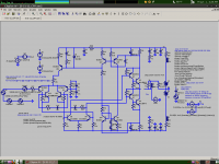
I am not having any overshoot issues in simulation with the CFP version. At first I was skeptical it could work with just 45uA input pair current, as the Ft at this current should theoretically be around 8MHz. But, the Ft spec in many situations isn't very useful. Just to be sure, I've increased the input pair current to over 500uA.
This version gets -3db at 5MHz. I don't see why any feedback capacitor is necessary.
This version gets -3db at 5MHz. I don't see why any feedback capacitor is necessary.
Attachments
Looks OK, but let us examine Keantoken's contribution before going further.Are these good?
See how they match?
Yes, but the compensation components you used are very different.I am not having any overshoot issues in simulation with the CFP version.
........
This version gets -3db at 5MHz. I don't see why any feedback capacitor is necessary.
This compensation strategy looks much more agressive, but if it doesn't harm the performances, it could be the way to go.
A fresh look from an outsider often brings interesting new things, and I welcome it.
I was a bit stuck with a somewhat unsatisfactory scheme, and if the issues could be solved that simply, that would be nice.
Have you looked at the slew-rates?
All I ever used to get compensation values was trial and error, informed by bode plots.
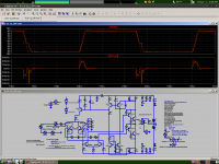
Here is the slew rate and an updated schematic. Redtrace is with no load, orange trace is with 6R load.
The feedback employs a capacitive divider that doesn't add any poles to the response and makes the feedback network good to the tens of MHz. This simplifies finding the right compensation values.
Here is the slew rate and an updated schematic. Redtrace is with no load, orange trace is with 6R load.
The feedback employs a capacitive divider that doesn't add any poles to the response and makes the feedback network good to the tens of MHz. This simplifies finding the right compensation values.
Attachments
Last edited:
- Home
- Amplifiers
- Solid State
- ♫♪ My little cheap Circlophone© ♫♪