The BCP56 is regular transistor size, possible to through-hole mount into good size via set into thick tracks. What also needs thick tracks is resistor drain since the resistor heat needs to be pulled away from the transistor--put the resistor heat into thick power rail instead.I ordered 50pcs Philips BCX56's for good price. I will solder their collector plate to a suitable copper heatsink.
However, the BCX56 version is very tiny SMD size. If using a normal soldering iron, you'll need a bamboo chopstick or kabob skewer to hold BCX56 down and prevent it from sticking to the soldering iron and/or escaping. Pre-tinning with Silver content solder and re-application of a thin film of Gel flux makes the process very fast. These need thick/reinforced tracks because they use both tab and pins for heatsink.
If you will not use them on smd pcb, their size difference doesn't make a lot of sense. BCP's leg distance is 2.3mm, BCX's 1.5mm, which is fair enough. What I like with BCX is its whole collector plate is naked Thus, if you attach/solder it to a wider plate, heat transfer from chip die should be done directly and more efficiently using its wider area. I didn't choose BCP's because you can only see a part of its collector plate.
Last edited:
I'm still soldering this little copperless perfboard version and its job is to make a nice new layout; however, it isn't conducive to test driving different parts and options.
Does anyone have a nicely spread out board for sale? One of the "RF proof" editions would be fantastic, despite the few jumpers.
Does anyone have a nicely spread out board for sale? One of the "RF proof" editions would be fantastic, despite the few jumpers.
I wonder MOSFET for Q5 & Q6? Would maintain input pair at more constant current?
Even with quadrature trying to disturb this, the collector resistor drops would drive
fixed gate threshold voltages, and no base current leak. Currents can't drift far from
this mark. R6 R7 obviously must scale up as VBE becomes a slightly larger VGS.
Wacky drain capacitance is my only concern. I don't know how to guarantee any
simulation behave realistic in that regard. IRF510 (100V,0R5) IRF610 (200V,1R5)?
either claims about 16pF, if only that cap would stay put and not squirm... You
got 820pF sandbagging from anode to anode, it seems reasonable in that light.
Is R5 in the second tail actually helpful? Considering its position within both
closed loops, the closed loop balance and non-shutoff here is already forced...
I was never all that clear about how one calculates loop stability to begin with?
And as we throw another loop at 90degrees effect into the blender, I get really
confused what effect the compensation is having upon each... If push and pull
are each doing nothing at some current minimum for slightly less than half a
cycle, differential compensation is clearly also active in the common mode loop.
I'm not saying that's a bad thing, it might be a good thing? Only it's an I don't
have a clue how to grasp for the math of it...
Last edited:
Not quite sim ready yet, just another half-baked noodling...
Not sure I got the fuzzy thresholds of the logic function quite right?
Pull the LTP up to try and shut it into class B. Then if either output
would actually threaten to go B and shut off, I pull down on the LTP
until the threshold of true shutoff is never quite met?
Moto 4N25A spec sheet suggests 1V15 to 1V5 might be threshold for
the LED? Seems a little too temperature dependent for the purpose...
Attachments
If you also do not connect a load, perhaps the drivers (Q9 Q11 schematic #1) alone
could satisfy the output stage crossing current rule? Be warned, if they conduct more
than 200mA continuously in attempt to do something stOOpid, like drive a load, or
fulfill a maladjusted rule requiring higher quiescent than 200mA, they will probably
burn up. If those drivers are not heatsinked, I would not even attempt it....
The outputs are also current dumpers for the drivers. Normally, drivers would never
be asked to conduct such current by themselves...
Last edited:
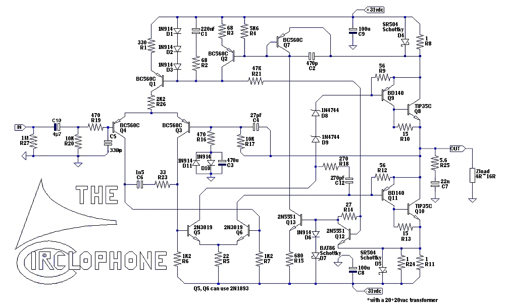
Right now I'm attempting a baseline example to see what a normal Circlophone could do. ♫♪ The Inexpensive Circlophone© ♫♪ It is very much like post 1 with some of the expense subtracted and a slightly different voltage, aimed at 4R to Tip35c, and seemingly keeping the parameters normal.
Unfortunately, I had managed to connect a possibly decent predrive to a erroneously haywired output section, somehow confusing a topside photo with a trackside photo, and that smells awfully. Visible damage looks inexpensive, with 1 Tip35c and 2 resistors nonfunctional.
However, the drivers need checked out somehow. The load that I was planning to drive with them is an ac voltmeter, hoping they can produce signal. For repair, I do have more ST Tip35c, but unfortunately, no more 2SB649 at the moment and I do not know if they survived my wiring error. I do have "Authentic Chinese" Fairchild BD140, which might not be that good, but of course might have to find out. . .
P.S.
HFE matching efforts reveal that NOS Philips BC556B is much like other manufacturer's BC560.
Last edited:
Daniel,
You should connect an old type 60W bulb in serial with your mains legs (like fuses on mains), just prior to the transformer. This is one of the thumb rules while first powering up an amplifier. When you see the bulb lights up shiny, you have to suspect something faulty on circuit. If you see bulb's filament in dully reddish color, you can begin to measure dc-offset and current draw by amplifier.
You should connect an old type 60W bulb in serial with your mains legs (like fuses on mains), just prior to the transformer. This is one of the thumb rules while first powering up an amplifier. When you see the bulb lights up shiny, you have to suspect something faulty on circuit. If you see bulb's filament in dully reddish color, you can begin to measure dc-offset and current draw by amplifier.
Muntz'd an entire current mirror, yet kept drain voltages ~ equal.
What more to be simplified and still obey laws of circlophonic logic?
I am still uncertain 4N25 optoisolator will conduct the required current.
The curves stop at 1mA, even though spec suggests it could go higher.
Maybe time to dig up the 9610 .model and see what LT thinks of it?
If the optos don't reduce complexity, really no point to them...
Attachments
C8 and C9, decoupling caps
Hi there Elvee: While making a BOM, I noticed that the decoupling caps mentioned in this post (10u/63v) are diferent from the schematic in post #1 (100u/100v)...which value should they be? ...regards, Michael
I missed that.
I am not sure it is a good idea: without a local decoupling, it won't be possible to achieve the transient cleanliness displayed in the oscillograms at the beginning of thread.
There is still plenty of room in the middle of your PCB, and it would certainly be possible to include at least a minimal on-board decoupling: nowadays, 10µ/63V caps are tiny, and they would make a big difference if there some length of wiring to the supply caps.
If you choose to include them, place the supply pads in close proximity, to avoid creating low impedance loops in the tracks.
I reiterate also about the respective placement of the output pad and the feedback take-up point: as they currently are, they will easily cause a doubling of the THD.
Hi there Elvee: While making a BOM, I noticed that the decoupling caps mentioned in this post (10u/63v) are diferent from the schematic in post #1 (100u/100v)...which value should they be? ...regards, Michael
It is a possibility, but it would have to be a matched pair: MOS have a large dispersion in the threshold voltage, and this would force Q3 and Q4 to run at different currents.I wonder MOSFET for Q5 & Q6? Would maintain input pair at more constant current?
Even with quadrature trying to disturb this, the collector resistor drops would drive
fixed gate threshold voltages, and no base current leak. Currents can't drift far from
this mark. R6 R7 obviously must scale up as VBE becomes a slightly larger VGS.
This would increase the distortion.
It is a concern, th Miller cap there has a strong effect, and it "mixes" the modesWacky drain capacitance is my only concern. I don't know how to guarantee any
simulation behave realistic in that regard. IRF510 (100V,0R5) IRF610 (200V,1R5)?
either claims about 16pF, if only that cap would stay put and not squirm... You
got 820pF sandbagging from anode to anode, it seems reasonable in that light.
Without it, the amp oscillates, in sim and (much more) in realityIs R5 in the second tail actually helpful? Considering its position within both
closed loops, the closed loop balance and non-shutoff here is already forced...
Compensation is rather messy. I have tried to keep both loops as independent as possible, and each is comfortably stable in its own right, but the mode mixing at higher frequencies creates unexpected effects.I was never all that clear about how one calculates loop stability to begin with?
And as we throw another loop at 90degrees effect into the blender, I get really
confused what effect the compensation is having upon each... If push and pull
are each doing nothing at some current minimum for slightly less than half a
cycle, differential compensation is clearly also active in the common mode loop.
I'm not saying that's a bad thing, it might be a good thing? Only it's an I don't
have a clue how to grasp for the math of it
I do not have a deterministic approach to cope with these effects.
Unfortunately, I had managed to connect a possibly decent predrive to a erroneously haywired output section, somehow confusing a topside photo with a trackside photo, and that smells awfully. Visible damage looks inexpensive, with 1 Tip35c and 2 resistors nonfunctional.
Be very careful not to leave a damaged component in place before making you next attempt. This includes low-values resistors, zeners, etc.
Be aware that some components might appear OK when tested with a multimeter, but could still be non-functional.
I would be very suspicious about your other TIP35: if one has gone, the chances are the other is also damaged.
I do not recommend testing the circuit without OP devices, it could do more harm than good, use the light bulb tester instead.
Hi there Elvee: While making a BOM, I noticed that the decoupling caps mentioned in this post (10u/63v) are diferent from the schematic in post #1 (100u/100v)...which value should they be? ...regards, Michael
The 10µ were advised in a "better than nothing" context, because of the lack of space, but the preferred value is 100µF.
I have simmed two BSS123 for Q5 and 6.I wonder MOSFET for Q5 & Q6? Would maintain input pair at more constant current?...
Seems to work transparently with R6 and 7 increased to 2K7, but this is a sim of course: the transistors are ideally matched, and in reality I am not sure it would be stable. It could certainly be made stable though.
An adjustible resistor for one VGS or the other then?
If the parts can't match, at least the currents can...
Trim for lowest output DC offset I suppose? I do not
think would need to measure those currents directly.
In #530, I have conspired to keep both drains > 40V.
Hopefully well above the zone where Miller tends to squirm.
That sim isn't playable yet, so I could be imagining things...
I would like if gate capacitance could save parts by being
also the dominant pole in both loops. Drain needs nailing
to some voltage constant before that becomes an option.
Last edited:
Well, this thing really rocks. Only problem is not nearly enough gain, and if I set the feedback resistor up to 18k, then there is enough gain but far too much upper treble (distorts snare drum). I'm using the Circlophone pictured in post 504. Perhaps one or more values need altered to bring down that treble a bit? Otherwise, it is an impressive amplifier.
In that configuration, the full power will be reached with less than 1V input.Well, this thing really rocks. Only problem is not nearly enough gain, and if I set the feedback resistor up to 18k, then there is enough gain but far too much upper treble (distorts snare drum). I'm using the Circlophone pictured in post 504.
With 18K, only 0.5V will be sufficient to reach the clipping limit.
That is probably what you're hearing. Otherwise, the amp is flat, and the characteristics are practically unaffected by the gain.
If anything, the high frequency response might just be infinitesimally reduced at a higher gain.
You could increase the input filter capacitor C5, but as I said the real issue is probably that you have reached the clipping limit.Perhaps one or more values need altered to bring down that treble a bit? Otherwise, it is an impressive amplifier.
You could try to fit one of the clipping indicators I have described. If you see the LED flashing when "there is too much treble", you'll know for sure the reason.
Daniel, could you give your impressions about the noise of your newly-built amplifier?
I am investigating that aspect:
http://www.diyaudio.com/forums/soli...cted-noise-benefits-circlophone-topology.html
I am investigating that aspect:
http://www.diyaudio.com/forums/soli...cted-noise-benefits-circlophone-topology.html
A new contender...
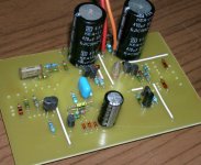
A new contender comes alive step by step.. This build has been almost a full "Dutch" Circlophone. I'm thinking about an elegant way for attaching heatsink for Philips BD140 drivers. Servo transistors not soldered yet.
Its companion will be the next.
Elvee: May you suggest a Philips made npn power transistor please?
Attachments
Last edited:
- Home
- Amplifiers
- Solid State
- ♫♪ My little cheap Circlophone© ♫♪