1). Large output devices, running a fraction of capacity, bolted to a good heatsink without thermal compound. 2). Replacing the output devices didn't fix the amplifier.
Possible cause: Power surge.
Suspected Q12/Q13, D7, D8/D9, D4/D5 one of these failed from overcurrent and/or overvoltage or ESD during power surge conditions. Perhaps you could test to see which need replaced?
Hello Daniel,
Thank you for advice. Actually I have replaced all transistors on pcb. When the resistors and diodes came to order, building a new one became more easier to me.
I have tried successfully BF459 and BF819.I can give a try for other alternatives of bias servo transistors in place of my 2n3020's. I wonder is there a beneficial role of Hfe value here? It is not hard to find some BF series high voltage transistors here like BF859/881 etc.
There are two possible pitfalls with this type of transistors: they have a "knee" voltage of several volts (the Vce voltage for which the linear performances begin to degrade because the transistor "runs out of steam"), and this will somewhat limit the output excursion, and the newer types have very low feedback and/or Cob capacitances.
This is normally considered to be a plus, , but if the capacitance is below 3 to 4pF, stability issues could begin to appear.
The circuit relies partly on the transistor's capacitance to self-compensate, and the recommended Cob range is 5 to 15pF.
4-20pF remains possible, this has been tested, but going beyond could lead to (minor) troubles. It also depends on Ft: if it is larger than 100MHz, lower capacitances could be tolerated, but the circuit will also become more layout-sensitive.
2N3020-type transistors are ideal for that purpose, and if you need to go higher in voltage, you can use heatsinked 2N1893.
Some suitable 2SC's have also been suggested earlier.
The Hfe is almost here irrelevant here, provided it isn't abysmally low.
@Terranigma,
Motorola 2n3019 (12pF, 100mhz), if you bought a few of them, could be HFE matched to 121, normally, or 150 at most. This is slightly more stellar than the other selections. Unfortunately, if you didn't plug them into your meter and match them up, the 2n3019 has a very wide span of variance. Those probably do need matched. Most decent digital multimeters have a transistor socket and HFE on the dial.
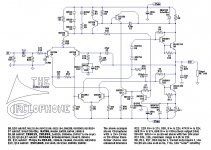
And, earlier your schematic/board shows option of R21 at 47k, meaning about 32v rails for total span of 64v. Perhaps Q12, Q13 needs to be one of these: 2SC1845, 2SC2240, 2N5550, 2N5551, transistors that can take voltage in excess of 65v. Guaranteed that an unregulated power supply is eventually going to pop BC546B at Q12, Q13.
Merely peculiar to my own notions, I'd like D7 as BAT86, and D8,D9 both at 1 watt capacity, and D4,D5 at least to 5a if not more and with voltage specs that appear to handle a rail even if such overdo may be unnecessary. One thing about modern diodes is that they tend to "glitch" randomly and so some fierce derating helps.
Oh, and. . . Arctic Ceramique has saved many thousands of chip amplifiers. It works on real output devices too.")
@Elvee,
Thank you very much!
Well, I had the documentation attempt, a bit off the mark. Here's a new copy with the sublist annotations fixed to represent capacitance at Q5,Q6, and the C5 is shown. I do have a question: What type of soft switch diode might be suitable to use at D10,D11?
Motorola 2n3019 (12pF, 100mhz), if you bought a few of them, could be HFE matched to 121, normally, or 150 at most. This is slightly more stellar than the other selections. Unfortunately, if you didn't plug them into your meter and match them up, the 2n3019 has a very wide span of variance. Those probably do need matched. Most decent digital multimeters have a transistor socket and HFE on the dial.
And, earlier your schematic/board shows option of R21 at 47k, meaning about 32v rails for total span of 64v. Perhaps Q12, Q13 needs to be one of these: 2SC1845, 2SC2240, 2N5550, 2N5551, transistors that can take voltage in excess of 65v. Guaranteed that an unregulated power supply is eventually going to pop BC546B at Q12, Q13.
Merely peculiar to my own notions, I'd like D7 as BAT86, and D8,D9 both at 1 watt capacity, and D4,D5 at least to 5a if not more and with voltage specs that appear to handle a rail even if such overdo may be unnecessary. One thing about modern diodes is that they tend to "glitch" randomly and so some fierce derating helps.
Oh, and. . . Arctic Ceramique has saved many thousands of chip amplifiers. It works on real output devices too.
@Elvee,
Thank you very much!
Well, I had the documentation attempt, a bit off the mark. Here's a new copy with the sublist annotations fixed to represent capacitance at Q5,Q6, and the C5 is shown. I do have a question: What type of soft switch diode might be suitable to use at D10,D11?
Attachments
Last edited:
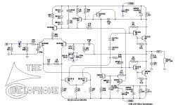
D10 and 11 are normally inactive. Their role is simply to keep the voltage across C3 within reasonable limits in case something goes wrong with the supplies powering sequence or similar event that could cause a latch-up.I do have a question: What type of soft switch diode might be suitable to use at D10,D11?
Practically, every silicon diode in the catalogue is suitable.
The simplest option is to go for the 1N4148, but you could as well use 1N4007 or BAT81, or zeners, varactors, PINs, you name it......
2n3019, 12pF, 121 hfe, vce 80v, 100mhz, (ST datasheet voltage)
2n1893, 15pF, 93 hfe, vce 80v, 50mhz, (ST datasheet voltage)
2n3501, 8pF, 150 hfe, vce 150v, 150mhz
There are several hundred of 2n3501 located about 85 miles from here. Motorola quality control(?) varies so much that given a 10 pack, about 20% may be down at hfe 121 same as 2n3019. Should I get some 2n3501 for Q5, Q6?
P.S.
It has a family: 2n3498 2n3499 2n3500 2n3501
Mea Culpa, I missed that one2n1893, 15pF, 93 hfe, vce 80v, 50mhz, (ST datasheet voltage)

There are several hundred of 2n3501 located about 85 miles from here. Motorola quality control(?) varies so much that given a 10 pack, about 20% may be down at hfe 121 same as 2n3019. Should I get some 2n3501 for Q5, Q6?
Yes, they look like excellent candidates.
If I can find some samples, I'll make an actual test, just to be sure, but normally it should be perfect.
@Terranigma,
Motorola 2n3019 (12pF, 100mhz), if you bought a few of them, could be HFE matched to 121, normally, or 150 at most. This is slightly more stellar than the other selections.
Yes, 2n3019 is a good choice up to 40V supply voltage. I haven't any problem with Motorola 2n3020's but sheets say that is a bit slower than 3019. If I could find 3019's from local suppliers, it would be good, otherwise it is not a big of deal anyway.
EDIT: "2n3501" looks like what kind of specs I've been looking for.
Last edited:
Maybe also. . .Yes, they look like excellent candidates.
If I can find some samples, I'll make an actual test, just to be sure, but normally it should be perfect.
6pF for NXP BCP56, granddaughter of Philips BC639/BD139.
http://www.nxp.com/documents/data_sheet/BCP56_BCX56_BC56PA.pdf
Is this long awaited answer to a "currently produced" high performance part for Q5, Q6?
In that case, the sublist looks like:
Q5/Q6 2n3498, 2n3499, 2n3500, 2n3501, 2n3019, 2SD669a, 2N3020, BF819, 2N1893, 2SC5171, BD139-8, NXP BCP56
I don't know if this list is completely accurate, but I really tried, and that is because I'd like to see good availability in parts for Circlophone.
P.S.
Derating, well, let's see if I got the concept:
Voltage, subtract about 16v from max tolerance or is there a rule of thumb percentage to use?
Output power, multiply datasheet brag by 0.75, like 200w output device x 0.75 = 150w useful?
Last edited:
BD139-8
How? Which datasheet specified the Ccb value of BD139?
For BD139/BD140, its either Philips or grotesque.How? Which datasheet specified the Ccb value of BD139?
Edit:
This problem is very misleading for post #1 and for post #504. At post #504, I had "best effort" for balanced parameters, as for sturdy parts doing what they should, but "inexpensive" is misleading since that schematic has an expensive collector's item for drivers. Sorry about that! I'll try to work up something else. I'm a newbie to discrete parts, so it takes a while. . .
Last edited:
Looks like a good candidate. At high supply voltages, care must be taken to provide sufficient PCB area for cooling (Pd=0.013*Vs)Maybe also. . .
6pF for NXP BCP56, granddaughter of Philips BC639/BD139.
http://www.nxp.com/documents/data_sheet/BCP56_BCX56_BC56PA.pdf
Is this long awaited answer to a "currently produced" high performance part for Q5, Q6? .
[QUOTEP.S.
Derating, well, let's see if I got the concept:
Voltage, subtract about 16v from max tolerance or is there a rule of thumb percentage to use?
Output power, multiply datasheet brag by 0.75, like 200w output device x 0.75 = 150w useful?][/QUOTE]
Things are a bit more complicated than that.
You can find informations on this forum and on other specialized websites, like ESP.
It seems Philips BD139 has 6pF level Cob which gets along with never BCP56's. Bad thing is i could only find Philips BD137's. They are at very edge with my 30V supplies.
http://www.diyaudio.com/forums/part...anyone-use-these-transistors.html#post1144733
http://www.diyaudio.com/forums/part...anyone-use-these-transistors.html#post1144733
There's several pairs to use for 4 to 16pF:
2sd699a, 2sb649
NXP BCP56, BD140
2sa1358, 2sc3421
2sa1930, 2sc5171
I find it interesting that the good drivers also have complimentary partners that could work for phase inverter. In addition to new production NXP BCP56, you also have the ever expanding list of NOS Motorola that, if given a big enough list, can make it possible to shop for them. I'm currently researching to126 and to220 subs, since the larger casing has some heat sink related convenience. There's many listed, but the question is which are available, so that takes a while to research.
I ordered 50pcs Philips BCX56's for good price. I will solder their collector plate to a suitable copper heatsink.
Philips NPN 80V/1A Transistor BCX56-10, SOT-89, 50pcs | eBay
Philips NPN 80V/1A Transistor BCX56-10, SOT-89, 50pcs | eBay
I did that once with some resistor packs. Dummy load...
soldered several to a big, skived, solid copper heatsink.
Easiest is with paste solder, and put the whole thing
in a reflow oven. Else the heatsink itself fights you.
Might be doable with a heatgun, if you can direct the
blast into the fins.
soldered several to a big, skived, solid copper heatsink.
Easiest is with paste solder, and put the whole thing
in a reflow oven. Else the heatsink itself fights you.
Might be doable with a heatgun, if you can direct the
blast into the fins.
- Home
- Amplifiers
- Solid State
- ♫♪ My little cheap Circlophone© ♫♪