Did you also use 2SA970's as input for your previous version?
Could you try to describe more accurately the kind of noise, or even better, capture a bit on wav file?
Yes, I can swap transistors by placed female pin headers. There is no difference with BC's and 2SA970's. As I said before, this noise problem is a known issue due to radio transmitters near my house. Same noise appears in my commercial equipment also. I don't want to bloat this thread with this specific problem.
OK, one last suggestion: try to remove completely C5: it might create a (tiny) low impedance RF reception loop within the LTP.I don't want to bloat this thread with this specific problem.
This effect could be damped by leaving R19 alone in the circuit.
Ferrite beads in the emitter leads might also help. It depends on the RFI frequency.
OK, one last suggestion: try to remove completely C5: it might create a (tiny) low impedance RF reception loop within the LTP.
This effect could be damped by leaving R19 alone in the circuit.
Ferrite beads in the emitter leads might also help. It depends on the RFI frequency.
Yes, It worked. I removed completely C5 and now I have silence again.
 It looks like that was what they call "microphonic effect" of ceramics. Just remained some very low level hiss that hard to hear closely which probably related with my cabling of current setup. Thank you for great support Elvee.
Not really microphonic, it is rectification/intermodulation of RF signals.It looks like that was what they call "microphonic effect" of ceramics.
The ambient RF level at your location must be truly horrendous for something like that to happen: normally, the input filter's role is precisely to keep this kind of signal out of the amplifier, but here the direct coupling with the magnetic component of the signal is sufficient to cause troubles.
You could try ferrite beads on the emitters and/or bases of the IP transistors, this might help.
So, Terra, Are you as utterly satisfied with the Circlophone as I am?
I use it in my everyday setup for both music and HT. All purpose. It is great at every task I give it.
Adding to that, I just moved into a new home and of course have a different speaker placement than before. The result: Yet another dimension of audio has been unveiled. Something wasn't optimal with my previous setup. There is much more depth -- and in result, detail -- to the sound.
Now, I have to make an addition to my Circlophone. I need to add a summing amplifier to output to my powered subwoofer. Elvee, what would you recommend regarding this? Right now I'm thinking simple summing op amp setup with an opa27 with its inputs in parallel with the Circlophone's. I can't think of a more simple or better arrangement than this.
It depends on how your system is organized.Now, I have to make an addition to my Circlophone. I need to add a summing amplifier to output to my powered subwoofer. Elvee, what would you recommend regarding this? Right now I'm thinking simple summing op amp setup with an opa27 with its inputs in parallel with the Circlophone's. I can't think of a more simple or better arrangement than this.
It could be as simple as a 2-resistor passive mixer, if the signal after your main volume pot is buffered and your sub has a high enough input impedance, or it could require two input buffers and one output buffer if you take the signal directly from the pot wipers and your sub is low-Z.
In any case, if an active circuit is required, the OPA27 should be transparent.
So, Terra, Are you as utterly satisfied with the Circlophone as I am?
I use it in my everyday setup for both music and HT. All purpose. It is great at every task I give it.
When criticize an amp, I have to take account my source anyway. In my point of view, amplifiers should reveal real capabilities of your source. As what Circlophone does. Despite all fancy words for describing things, I will just say that this amp makes me put a smile on my face while listening music. This is fair enough for me.. Am I utterly satisfied? Yes, indeed. But I'm not finished yet. I'm on trial for investigating effect of different components on sound signature. And I didn't try faster output devices yet.
Some great news:
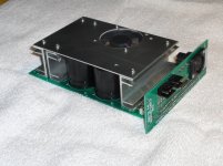
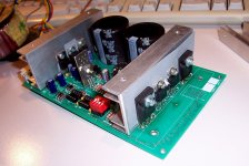
mickeymoose is about to release his PCB version for the Circlophone.
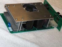
It is a complete one-channel module including the power supply, a balanced preamplifier, a fan, fan controller, auxiliary supplies, and a well thought out mechanical/heatsinking design.
Neat and compact, works like a charm.
Here is a preview of the beta version:
mickeymoose is about to release his PCB version for the Circlophone.
It is a complete one-channel module including the power supply, a balanced preamplifier, a fan, fan controller, auxiliary supplies, and a well thought out mechanical/heatsinking design.
Neat and compact, works like a charm.
Here is a preview of the beta version:
Attachments
ELVEE:
Thanks for your patience in getting all of us this far with this amp!
Some additional info :
The board was designed to fit a DIN standard card-frame, size 100x160mm, the assembly is 1.8" wide
I will post schematics and layout info soon
All parts used are through-hole and standard, off-the shelf
If there is enough interest in a group-buy I see following parts included in the package:
2 pc boards (amp & back-plane), heatsinks (4 pcs.) and a programmed uP for the fan
E
Thanks for your patience in getting all of us this far with this amp!
Thank YOU for your dedication!

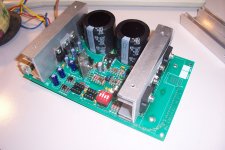
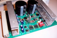
Here are some more pics of the "innards" (always the prototype of the beta version):
Attachments
Last edited:
The cost of the "kit" depends on what you expect. The easiest for me (and cheapest for you) is just the boards and pre-cut heatsink parts (drill your own holes), it is diy audio, after all. The code for the fan controller will be available (not yet written, any one willing to do that?)
Cheers, and lots of presents to all! E
Cheers, and lots of presents to all! E
for me it's all the same actually.
I'm getting some symasym boards in a few days and that will be my first. So i dont have any experience in all the diy stuff. So I'll have to buy a hole-maker and all, but hey... i'm gonna need it anyway, so i don't care!")
ps. isn't it "safer/easier" do use transistors to drive the fans instead of a micro controller? something like this, but with a thermistor or so to regulate:
Simple Linear Fan Controller
I'm getting some symasym boards in a few days and that will be my first. So i dont have any experience in all the diy stuff. So I'll have to buy a hole-maker and all, but hey... i'm gonna need it anyway, so i don't care!
ps. isn't it "safer/easier" do use transistors to drive the fans instead of a micro controller? something like this, but with a thermistor or so to regulate:
Simple Linear Fan Controller
Hi,
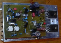
i made a circlophone based on powerfluxes pcb (see the attached picture). I did use the transistors originaly proposed in the schematic. Voltage ist +-25V.
Power draw (no signal) from Transformator is approx. 10W.
First impression (using cheap speakers): Good bass and mids.
The only problem i am experiencing: The driver Transistors and 2n3019 are getting too hot to touch. Did anybody else a build usind the tight packed powerflux pcb? Is there a clever way to use a heatsink on the to-39 package?
Thank you.
Attachments
Hi,
i made a circlophone based on powerfluxes pcb (see the attached picture). I did use the transistors originaly proposed in the schematic. Voltage ist +-25V.
Power draw (no signal) from Transformator is approx. 10W.
First impression (using cheap speakers): Good bass and mids.
The only problem i am experiencing: The driver Transistors and 2n3019 are getting too hot to touch. Did anybody else a build usind the tight packed powerflux pcb? Is there a clever way to use a heatsink on the to-39 package?
Thank you.
i've made a mistake: 15R and 56R on bottom BD are reversed on silkscreen. this has been noted before but here i've uploaded a corrected PDF-document.
Other improvements are more space for cooling for the BD's. if one doesn't use the jumper, or solders one on the bottom, one can use a flat standing piece of aluminum across the PCB for both BD's together. but do remember to use isolation (mica or silicone)
i call this V2.0, and the power transistors are TO-264
Attachments
Last edited:
- Home
- Amplifiers
- Solid State
- ♫♪ My little cheap Circlophone© ♫♪