Direct comparison was becoming more difficult as the design
drifted away in a few details that weren't necessary to differ.
I put drivers back in, as they were needed to handle 4 ohm.
Sorry not the same BD140's. I kinda painted myself into a
corner where only an NPN would work, 2n3019 volunteered.
I also lowered the quiescent, so it crosses more similar to
Elvee's Circlophone. Could use a little more tweaking here,
as I think I still have my reserve current set slightly higher.
Attachments
Something ugly happening in this output stage now in hard clipping, ???
Quick and dirty fix is to soft clip the VAS, rather than the global loop.
Just disconnect lower end R15, and reconnect to the wire on it's right.
Soft clip is no longer symmetrical, but the hard problem was worse...
Just till I figure some better way to fix it... I may have output drives
biased a little lower than I should.
This one looks quite nice and well behaved.
There seems to remain some work to do in the dynamic behavior/large signal department, as the waveform at 20KHz looks visibly distorted, but at this stage, actual physical tests would be needed to ascertain the effect, and refine the design if necessary since the sim may not be quite reliable for this aspect.
Compared to the Circlophone, it is somewhat simpler (3 small signal transistors less) and has slightly lower performances, but the most important differences are elswhere:
-It is built around Ken's pet obsession with schottky's to shape the crossing.
-It has a less deterministic control of the quiescent current and output crossing.
The Circlophone servoes very tightly those parameters in the low power/control circuits, whereas "Converge" works directly at the output level, utilizing the I/V characteristic of the schottky's as a template.
Both approaches certainly have their merits.
In the Circlophone I wanted to completely eliminate the dependency on components, thermal couplings and ambient temperature: you can use any schottky's, any power transistors, any low power transistors, it always work identically, any spread being absorbed by the servo. In fact, you could even include one germanium in the mix, it would still work.
In "Converge", the quiescent current will depend on the type of schottky, their temperature, the saturation current of the sense transistor, etc.
But it will give a special "taste" or colour" to the output stage's transfer.
It would be a good idea to launch a dedicated "Converge" builder's thread to put these ideas to the test.
Back to the Circlophone.....
I have built one more variant, this time with BD249's as ouput devices.
The purpose of this version was to test the design under extreme conditions, in this case a very low impedance load.
Some "exotic" speakers have an impedance <1Ω, and few amplifiers are capable of driving such a load directly, without a transformer.
I made a test on a 0.5Ω load.
This pushed the transistors to their limits, at >25A Ic, but the Circlophone remained steady as a rock.
The sim uses TIP35's, as I couldn't find models for the BD249C, but they are very similar.
This illustrates how tolerant, flexible and healthy the design is.
Of course, the THD is increased compared to 4Ω, but it remains quite acceptable, especially taking into account the fact the transistors are really pushed to their limits (and beyond).
Attachments
Member
Joined 2009
Paid Member
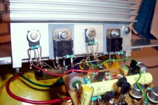
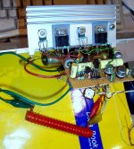
Here are some pics of the above-mentioned version:
The feat is made possible thanks, amongst other things, to the absence of emitter resistors: in a standard topology, with a 0.5Ω load impedance and 0.22Ω emitter resistors, practically half the equivalent of the useful amount of power dissipated in the load is wasted in the resistors.
In the Circlophone, the only obstacles to the current flow are high-current schottky's, and the transistors themselves.
The BD249 are rather cheap and crappy, and with better devices, loads even lower could be handled with a better efficiency.
But the Circlophone is not simply about brute force.
In a completely different domain, at a gentle power level and on more "normal" loads, the performance is on the par with a good, pure class A amp:
Attachments
There seems to remain some work to do in the large signal department.
Yeah, yours too... (1V Input)
Do I see transistors turning off?
Q1 Q2 Q3 Q4 Q5 Q6 Q9 Q10 Q12
Laugh again my non-determinstic clip and crossings?!?
Hold that egg in too tight a grip, this what happens.
Attachments
I can do deterministic too.
Abuse a threshold narrow enough, Schottkys must cross class C.
Then set your deterministic class A crossing with two resistors.
Plus always-on bypass current...
Near as I can tell, its bias logic exactly the same as circlophone.
Though can't quite set my bias as low, on account of bootstrap.
Input here was 0.7 so I could compare apples to Circlopone M's..
Attachments
Sorry if I offended you, that was certainly not my intention.I can do deterministic too.
Abuse a threshold narrow enough, Schottkys must cross class C.
Then set your deterministic class A crossing with two resistors.
Plus always-on bypass current...
Near as I can tell, its bias logic exactly the same as circlophone.
Though can't quite set my bias as low, on account of bootstrap.
Input here was 0.7 so I could compare apples to Circlopone M's..
Since you chose this thread to display your ideas, I gave my opinion, and made some comparisons.
I made comparisons, but I don't think you interpreted them correctly.
I just meant that you solve the problem using an "open loop" approach, where my solution is a more "closed loop" one, where things are more tightly under control.
This is not a value judgement, more the observation of a difference.
Both ways have advantages of their own, and it is impossible to decide in absolute terms which one is the best, if there is such a thing.
To be honest, I find the final version of the Circlophone looks quite clumsy, inelegant and over-complex.
I started with something cleaner, more symetric and more elegant.
But I reworked it, made many actual tests, and arrived at the painful conclusion that a rather messy circuit was ultimately the optimum solution.
In the end, I settled for something rather ugly, but effective.
I wanted to tightly control the quiescent current and crossing regions, as I said, because that's where most of the problems associated with conventional class AB occur.
I never said I wanted to control the clipping conditions in the same way: that's one of your own preoccupation, which I don't necessarily share.
I just wanted to make sure the "outside" behavior was decent, no more.
I haven't included "clean" or "soft" clippers: I just made sure the clipping behavior, as seen from the load remains clean, but without attempting to soften or improve it.
As you have pointed out, the slow transistors struggle to get out of saturation, and they are "nudged" by their counterpart to do so, but the process remains completely transparent to the load: the clipping is clean and the recovery is clean too.
See the pic of the output voltage during clipping (the actual waveform is identical to the sim).
There are spikes of current in the OP stage, but they remain moderate, and perfectly manageable by the OP transistors, and this has been abundantly tested in reality.
I didn't want to control further the clipping behavior, that's my design choice, you made another one, you are free to do so, OK why not, but I'm also free to do mine: I consider clipping should be exceptional, and that a clean behavior is sufficient, period.
If I said the dynamic behavior of your circuit could be improved, I didn't mean the clipping: I meant slew rate and power bandwidth.
As I said, clipping is a secondary consideration for me, but I think a decent behavior at 20KHz does have some importance.
I am not an extremist in that matter, unlike many on this forum, but I think a decent margin is desirable, and achievable without too many difficulties, even using rather crappy components, as I do.
If you examine the power bandwidth of your amplifier, you will see that there is room for improvement.
I was cautious in what I said, because the physical version of the Circlophone did much better in this respect than the sim, and that was verified with all 2N3055 brands, without exception.
But where there are obvious shortcomings, they should be remedied.
One more thing:
I do not want to look patronizing, or hurt your feelings
If you think/feel I am, this is in no way intentional.
I think you are one of the most creative members of this forum, and I think your latest creation, the active tail control for the LTP is great.
I have even tried to find ways to include it in the Circlophone, but unfortunately, the two principles look mutually exclusive.
But it will stay in a corner of my mind, available for a future use.
Attachments
Nope, I'm not offended. Hope you're not offended.
I blame Bigun. No reason, it just feels so right...
Was not my intent to pass off phoney circlos...
Just trying to clarify a circuit that I difficulty
wrapping my mind around. It was several days
before I even realized that it performed the
same computation I had been working on...
I blame Bigun. No reason, it just feels so right...
Was not my intent to pass off phoney circlos...
Just trying to clarify a circuit that I difficulty
wrapping my mind around. It was several days
before I even realized that it performed the
same computation I had been working on...
No problem, I think each of the two approach has its own merits, and there is room enough for both.Nope, I'm not offended. Hope you're not offended.
I blame Bigun. No reason, it just feels so right...
Was not my intent to pass off phoney circlos...
Just trying to clarify a circuit that I difficulty
wrapping my mind around. It was several days
before I even realized that it performed the
same computation I had been working on...
I suspect your version will appeal more to a number of members of this forum: it is more straightforward, and doesn't include a rather complex servo loop, as the Circlophone.
It is true that in a more complex system, there is more space for things to go wrong.
I took great care in ironing out any potential issue, I tried to leave no stone unturned (or maybe the opposite) to make sure the thing is 99.99% reliable.
But many won't trust the system and will prefer your way of doing things.
I cannot blame them, and generally I prefer this kind of topology too, but I found no way to achieve my goals without adding some complexity.
The result is not very elegant, but it is astonishingly effective, and so far it looks foolproof.
Thank you Elvee for sharing with us this beauty. I always respect to intelligent potential and kindness spirit of this site.
I'm planning to build this amp as four channels due to my active speaker requirements. As normally, I'm using balanced signal for each channel. Has circuit any potential to modify input stage to accept balanced signal without referencing to ground? If no, that is not so important at all.
I like to use oldschool parts in new designs, especially TO-3 ones. I got plenty of devices like:
Motorola 2n3773 (Vcbo=160,Vceo=140)
Toshiba 2sd110 (Vcbo=130, Vceo=110, 1mhz, 200pF)
Motorola MJ15003 (Vcbo=140,Vceo=140, 2mhz, 1000pF)
Motorola 2n3055
I think it is easy to maintain 80-100W with a pair of these using proper driver transistors and rails.
I got some choices of DC rails like: 31V, 36.5V, 62V. I think 36.5V a bit low for 80-100W range. As you mentioned in post 182, 31V rails are enough to get 50W. Maybe i have to go with it if I can't bear build a LM338 based regulator for drop 62V to 42V.
Regards.
Member
Joined 2009
Paid Member
I blame Bigun. No reason, it just feels so right...
what ? me ?

...

Last edited:
Here's a sample redraw, based upon Circlophone M.
Models are all still there, just above the screenshot.
During the redraw, I have come to question R19's
purpose? Appears only to bias Q12 into saturation.
Its exactly like this in the original, so I have to ask.
Was this an oops? Intended as a base stopper???
I haven't commented any part of the circuit yet.
Attachments
Last edited:
Member
Joined 2009
Paid Member
During the redraw, I have come to question R19's
purpose? Appears only to bias Q12 into saturation.
Its exactly like this in the original, so I have to ask.
Was this an oops? Intended as a base stopper???
I think I asked the same question, only it was R14 when I asked it...unless I'm confused the explanation is here:
http://www.diyaudio.com/forums/solid-state/189599-my-little-cheap-circlophone-9.html#post2680046
Using the (-) input of the amplifier seems risky, as the source impedance would influence the feedback.I'm planning to build this amp as four channels due to my active speaker requirements. As normally, I'm using balanced signal for each channel. Has circuit any potential to modify input stage to accept balanced signal without referencing to ground? If no, that is not so important at all.
This could lead to problems, and I would not recommend it.
If you can be a bit patient, the next PCB version will include a preamplifier with a balanced input.
It is being finalized, and should be available soon
They are all suitable, and if you aim at 100W the MJ15003 seems perfect.I like to use oldschool parts in new designs, especially TO-3 ones. I got plenty of devices like:
Motorola 2n3773 (Vcbo=160,Vceo=140)
Toshiba 2sd110 (Vcbo=130, Vceo=110, 1mhz, 200pF)
Motorola MJ15003 (Vcbo=140,Vceo=140, 2mhz, 1000pF)
Motorola 2n3055
I think it is easy to maintain 80-100W with a pair of these using proper driver transistors and rails.
You don't need other drivers, some of the other transistors may need a higher Vceo if you go for 42V rails.
The original drawing is purely graphic, and didn't evolve. The functional versions are messier.Looking back, the original Circlophone drawing wasn't bad.
It grew slightly less organized as it evolved...
You did a nice cleaning job, thanks for the effort.
Anyway, here is the asc of the graphic version, if someone wants to play with it.
Attachments
Using the (-) input of the amplifier seems risky, as the source impedance would influence the feedback.
This could lead to problems, and I would not recommend it.
If you can be a bit patient, the next PCB version will include a preamplifier with a balanced input.
It is being finalized, and should be available soon
My concern is C3, coupling cap at input. My source has DC if it refers to ground, thus requires a cap at input of amplifier which is a compromised solution that I dislike -imho-. If I use balanced as source, then there is no ground referenced signal and there is no DC, then there is no need a cap in signal path. It is fair enough to put a speaker protection at output for possible failures.
I'm a lazy builder, then there is no hurry for me
Regards.
PS: If you ever build/listen an amp based on LME49810's.. can you compare them?
Last edited:
- Home
- Amplifiers
- Solid State
- ♫♪ My little cheap Circlophone© ♫♪