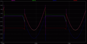
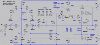
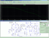
OK, I have disabled soft clipping, and overdriven to saturation and latchup.
You can see the active tail can and will rescue from the latched condition,
but only seems able to achieve this over half the input cycle. Better than
having to pull the plug and start over, I suppose....
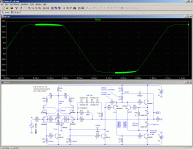
While this was going on, the output looked a fully clipped squarewave, just
as you would expect from normal clipping. Output phase not reversed or
anything weird that would alert the listener to the temporary latch...
Attachments
Last edited:
Here's what I got so far.
If you include the .ic, the circuit remains stuck.
This means that in practice it will, that's why clipping schottky's are indispensable.
Attachments
It is an initial condition.Exactly what is this .ic thing are you including?
I thought you just meant measure collector current?
By default, the simulator makes no assumptions about the initial voltages of any node (except for ground and where there are voltages sources with Rs=0).
By specifying an ic, you can force force an initial current into an inductor, or a voltage at one or more node, either to make the sim converge more quickly, or to test the effect of some condition or event.
Here the base of Q2 is n(008) (generally a good idea to rename it to avoid name changes each time the circuit is modified).
I forced it to 2V to see how the circuit would recover after a transient event (typically power-on, or some sort of spike).
Attachments
And you are saying input diodes will rescue from 2A .ic?
I think between my soft clip, and active tail, I'm at least
as well protected against 2A suddenly and mysteriously
appearing in a circuit that normally conducts 3.25mA.
Negative resistance is only a dynamic slope. Even in the
worst latch, its not going to conduct more than 50 volts
into 1224.7ohms. 40ma worst cased, not 2A...
----
Wait, now its 2V, not 2A? I am completely confused...
You never answered my silly question about DIACs or
Tunnel Diodes, or basakwerdz oldskool 2n2222 negistors
as base stoppers in a negative resistance amplifier.
If regular resistors get inverted and make it less stable,
what happens with stoppers that are negative to begin?
Last edited:
In theory it would be possible. In practice, it would be like jumping in the swimming pool to avoid the rain.You never answered my silly question about DIACs or
Tunnel Diodes, or basakwerdz oldskool 2n2222 negistors
as base stoppers in a negative resistance amplifier.
If regular resistors get inverted and make it less stable,
what happens with stoppers that are negative to begin?
Diacs are not practicable anyway, they require ~30V to function, and they do not have a continuous characteristic with a defined negative slope, they mostly break down.
Tunnel diodes should be more suitable, but given their price, rarity, and the necessity to bias them very accurately, they are not practical either.
It is not caused by the diodes themselves, , it is just that the amplifier is marginally stable, and the .ic is sufficient to trigger oscillations when the amplifier recovers.Doesn't latch anymore, but oscillates like mad...
It is just a symptom of the marginal instability of the global loop.
This is confirmed by the apparition of oscillations when the amplifier is overdriven:
Attachments
I observe no such oscillations in clipping until I add your Schottky diodes.
(0 1 1 K) (0 1.25 1K) (0 1.5 1K) (0 2 1K) (0 2.5 1K) all simulate fine.
2.5 moves us beyond soft clipping into genuine hard clipping
recovers a little weirdly from this, but still isn't oscillating.
Add your pair of BAT54, now anything over 1.25 oscillates in clipping.
-------
Diodes, what diodes? I was talking about an x stacked upon an x.
Yes, it oscillates... Too bad, since I was hoping it might avoid the
reversal in saturation issue by dubious "virtue?" of reversing twice.
I don't have any models for a real negative resistance diode.
Last edited:
That is correct. But replacing them with a 10p capacitor is sufficient to create oscillations.I observe no such oscillations in clipping until I add your Schottky diodes.
This means that the stability is very marginal.
And if the timestep is decreased to 100ns, it oscillates with C=0.
The overall loop margin is probably much too small, and because the conduction of the zeners shifts the closed loop gain towards unity, that's sufficient to cause oscillations.
Waow, that's a really weird one: and it really works, the phase of the current is reversed.Stranger still, LTSpice doesn't complain when I give a resistor a
negative value (-4.7R) and abuse as base stoppers in the X...
Probably time to make some proper loop stability analysis.
A quick and dirty check shows that the margin, under quiescent and unstressed conditions is ~15°. It is a bit short, to say the least.
When you make a pact with the X-devil, you can't get away without letting go something dear in exchange for the improved linearity and loop gain
I didn't opt for a X-quad in the Circlophone, yet (or because?) I already have a 15~20yrs experience with this topology.
But when you do your homework, it can be very rewarding. And Eva's version is a good tradeoff between performance, complexity and ease of use.
Attachments
Add 47R in series with CDOM, and eliminate 33pf + 47R in the return path.
What are considered basic victory conditions for this test of stability?
I know 180 deg at 0db (unity gain) would be an obvious fail, but how
much gain we allowed at 120deg? 150?
What are considered basic victory conditions for this test of stability?
I know 180 deg at 0db (unity gain) would be an obvious fail, but how
much gain we allowed at 120deg? 150?
Attachments
Last edited:
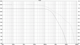
Closed loop response is not very telling.Add 47R in series with CDOM, and eliminate 33pf + 47R in the return path.
What are considered basic victory conditions for this test of stability?
I know 180 deg at 0db (unity gain) would be an obvious fail, but how
much gain we allowed at 120deg? 150?
What you really need is an open loop plot.
That said, it doesn't look bad: the amplitude has no peaking, although the slope increase at ~5Mhz could be of concern but combined with the phase response, there is no obvious danger signal.
For a quantitative evaluation, a real Bode plot is necessary.
The way I do it is simplified and unorthodox, but in this case, and if you understand what you are doing, it is more than sufficient for a quick evaluation.
Insert the stimulus at a single point of passage of the signal (ie, if it's cut there nothing can pass elsewhere), and make sure the source has a much lower impedance than the receiver, that way you can dispense with the complete transfer matrix required in a general case.
That's what I did on the pic above, in #234.
But that won't reveal anything, except marginal phase, since the analysis is made under quiescent conditions: oscillations occur only near saturation, and/or at unity gain.
To chase them and iron out any possible instability, you need to explore those conditions/combinations of conditions too.
But obviously, if stability is already marginal under gentle conditions, it will be worse under stress.
Which is why the static stability has to be addressed before anything else is attempted.
Member
Joined 2009
Paid Member
What difference? Maybe I'm not seeing it?
Both have secondary feedback in quadrature
to the noble loop. And for the same reasons...
Maybe you are confused cause Elvee's peasant
loop senses current from the outsides. And my
example senses this same current from within.
Otherwise same exact thing, completely different.
Besides, its all the art of rounding corners of the
schematic. Them hard simulated turns, all fun and
games till someone puts out an electron! Running
in the hallway with scissors, xquads or whatever...
Earlier in this thread, my peasant loop returned
this feedback all the way back to the LTP's tail,
exactly same as Elvee's. But I later found that a
much shorter peasant loop functions just as well.
Last edited:
+/-25V rails, check!
2n3055 finals, check!
2n3019 VAS, check!
10K+470R Input and GNF Z, check!
22x voltage gain, check!
Peasant loop in quadrature, check!
Active tail modullation, check!
No transistor ever turns off, check!
Nice round corners, check!
PNP LTP, check! Fell off the BC556B
wagon somewhere, but easily fixed...
No similarity whatsoever...
Last edited:
Member
Joined 2009
Paid Member
What difference? Maybe I'm not seeing it?
Both have secondary feedback in quadrature
to the noble loop. And for the same reasons...
that's great - because it looks to be less complex. If I understand then, the front end no longer controls the sliding bias, it's function is purely to be a voltage error amplifier.
- Home
- Amplifiers
- Solid State
- ♫♪ My little cheap Circlophone© ♫♪
