Replace the two Zeners with one NPN in cascode?
I mean w. base referenced to output...
Q6 already rides one emitter (Q11) below the output,
both Q5 & Q6 should then see same collector voltage.
Here is this idea put to the test: once again, the change is almost insignificant (-2ppm), but at least, it's in the good direction.
Attachments
Right!Should the 270R + 820P span across the top of the cascode?
There is no visible effect on performance however, since the sole purpose of this network is to improve stability.
Attachments
Oops!Cascode side move looks right, but other side of 820p now connects
Q13 Q10 Q9 instead of Q4 Q6. Subtle reason for this, or simple oops?
In fact those transistors form an "AND" gate but in the analog domain: for Q2 to conduct (and thus to reduce the quiescent current via the common mode loop), a voltage has to be present across R8 (i.e. a current must flow into Q8) AND the compensating transistor Q7 has to be biased, which requires Q13 to conduct, and therefore ultimately Q10 too (Q12 is just a compensating transistor).Elvee, could you explain a little how the bias servo operates? I don't completely follow how the network of Q2, Q7, Q12, and Q13 works
The subtlety of the circuit is that it doesn't simply work digitally, but in an analog manner too: if the current in one of the output transistor is lower, this can be compensated within certain limits by an increase in the other one.
The result is that the currents can never fall below a minimum of 80mA, and vary in a complementary manner.
This also forces both OP transistors to always remain active, and I mean really active: it isn't simply a "passive" bias current superimposed on the working current: not only is each transistor active, but so is the whole upstream circuitry, up to and including the input stage.
This means that the OP transistors play no role in deciding the amount or the repartition of the quiescent current, nor the output current's value.
This is decided at a signal level, and is the result of the "negociation" taking place between the two control loops: the "noble" differential one and the ancillary common mode one.
Here is the schematic again for an easier reference.
Attachments
The result is that the currents can never fall below a minimum of 80mA, and vary in a complementary manner.
This also forces both OP transistors to always remain active, and I mean really active: it isn't simply a "passive" bias current superimposed on the working current: not only is each transistor active, but so is the whole upstream circuitry, up to and including the input stage.
This means that the OP transistors play no role in deciding the amount or the repartition of the quiescent current, nor the output current's value.
This is decided at a signal level, and is the result of the "negociation" taking place between the two control loops: the "noble" differential one and the ancillary common mode one.
And why are we the only ones currently proposing circuits with
two such simultaneously active cooperative feedback loops?
And why are we the only ones currently proposing circuits with
two such simultaneously active cooperative feedback loops?
I think there are two main reasons: one has to do with tradition/habits/fear of the unknown, etc, and the other is a (partially) justified distrust of something (felt like) over-sophisticated, over-complicated and too delicate to work in practice.
And it is true that the audio history is littered with many examples of servo schemes failing to deliver, or even going plainly wrong.
The Visch circuit is a good example: under near-steady conditions, it seems to work beautifully, but as soon as you begin to shake it a bit too hard, it messes things up big time.
All this can explain the suspicion and doubts of experienced guys like Wavebourn f.e.:
http://www.diyaudio.com/forums/solid-state/189599-my-little-cheap-circlophone-3.html#post2589178
http://www.diyaudio.com/forums/solid-state/189599-my-little-cheap-circlophone-4.html#post2589382
http://www.diyaudio.com/forums/solid-state/189599-my-little-cheap-circlophone-4.html#post2589609
On the other hand, even an ugly little duckling like this one can be made to work (sort of) by an amateur. Potential problems are well-known, as are their solutions.
This state of mind might be reversed if we succeed in coming up with simple, effective, robust and problem-free designs.
Was messin with your front end and finals grafted with a centralized quiescent control.
I come to realize both loops need independent compensation for stability. But I have
not yet mastered how to make (two schottkys, resistor, transistor) completely stable.
I return a control current to the 330R at the emitter of whats Q1 in your drawing...
Base of Q1 is simply biased by two diodes and 1mA. Works fine up to about 8K, but
anything above makes the whole sim go completely nuts...
Wasn't ever stable till I axed one stage of drivers.
But then I had to flip the whole front upsidedown.
Had no idea what I was doing, random experiment.
Stability still goes bannanas whenever it clips.
Recovery from clipping here is just plain awfull.
I would soft clip this with Zeners across R11.
One 2n3055 gets an assist from base current, the
other dumps base current into the negative rail.
So the collector currents will never be symmetrical.
Took me a while to realize I should stop obsessing
for a perfect current balance, not posssible...
Attachments
Last edited:
Stability aspects of this topology are somewhat disconcerting: you can't use the old recipes applicable to traditional topologies.Wasn't ever stable till I axed one stage of drivers.
But then I had to flip the whole front upsidedown.
Had no idea what I was doing, random experiment.
Stability still goes bannanas whenever it clips.
Recovery from clipping here is just plain awfull.
I would soft clip this with Zeners across R11.
One 2n3055 gets an assist from base current, the
other dumps base current into the negative rail.
So the collector currents will never be symmetrical.
Took me a while to realize I should stop obsessing
for a perfect current balance, not posssible...
The schemes and values I arrived at are largely based on trial and errors, most of them on the physical circuit because the sim is not quite reliable for dynamic aspects.
In addition, I've noticed on your "nothing to see" design that the current sensing via the schottky's seems to generate or at least facilitate some instabilities: I had to add an emitter degeneration resistor on the sensing transistors to achieve complete stability with a 1µs timestep.
Both loops stable now.
Also ditched a resistor only needed in MOSFET version.
Distortion reasonably low, considering 2N3055 at 750mA crossing.
And 165mA of that bias is always on, bypassing both Schottkys.
I am assuming "circlo" refers to how the bias servo returns full
circle, to regulate the tail CCS? My second loop compensation
loosens the harsh grip it has upon this at higher frequencies.
Things get weird if common and differential loops roll too close
same corner frequency, easily avoided. Resistors in series with
caps take gains down without rolling the phase too much, and
FT somewhere I havn't determined where (probably 2N3055?)
does final roll.
The 15R's could be parallel 33R's to enhance BOM monotony.
47pF = parallel 100pF, 1N4148 = diode strapped BC546B,
22K = series 10K's, etc... Too many different parts always
a shopping nightmare.
Attachments
Last edited:
Both loops stable now.
Also ditched a resistor only needed in MOSFET version.
Distortion reasonably low, considering 2N3055 at 750mA crossing.
And 165mA of that bias is always on, bypassing both Schottkys.
I am assuming "circlo" refers to how the bias servo returns full
circle, to regulate the tail CCS? My second loop compensation
loosens the harsh grip it has upon this at higher frequencies.
It looks pretty stable, even without the CM compensation network.
It remains almost perfectly behaved, even when clipping.
The schottky's as current sensors give a very nice crossing.
Have you tried it in reality?
Is it thermally manageable?
Attachments
Schottkys are selected for overkill sized TO220 package.
But due low voltage drop, rarely dissipate more than 1W.
Current sensors should be ambient temp, NOT thermally
bonded to outputs. OK to thermally bond diode to diode,
we want crossing curves to behave as a matched pair.
Q8 should be thermally bonded to same sink as outputs,
I think then you have an ideal situation for locking into
equilibrium between operating current and temperature.
As Q8 gets hot, all other quiescent currents decrease.
If Q8 itself runs away, the amp safely shuts down...
Last edited:
Current (especially the minimum) in each 2N3055 a little more equal.
I don't have any flash of inspiration how fix the remaining imbalance.
What do do about current from base to emitter of the upper 2N3055?
This imbalance isn't bugging me anymore: at the beginning of my experimentations with circlo output stages (= same sex devices but not quasi), I tried to find ways to balance the currents better, but with experience I've found there is little to be gained, quite the opposite.
Now, I happily live with it. It may be intellectually disturbing, but the real impact is very limited.
I think I'll give a try to the schottky sensors one of these days, to see what it's really worth in practice.
I am not sure coupling Q8 to the OP transistors is the best option: coupling it to the diodes might be a valid option too.
?
Hi Kenpeter,
in my simulator b2spice
at 19V pp output @8 ohm
I have heavy oscillations of the sine wave,
I used different shottkys (10tq045)
might this cause the oscillations?
Both loops stable now...
Hi Kenpeter,
in my simulator b2spice
at 19V pp output @8 ohm
I have heavy oscillations of the sine wave,
I used different shottkys (10tq045)
might this cause the oscillations?
Schottkys should only be affecting shape of the crossover region.
Diodes doing nothing significant at 19V that could initiate oscillation.
I prefer to worry that cascode Q9 might be a positive feedback
into the Miller of Q5? Perhaps attenuate higher frequencies from
reaching the base of Q9 would help. Ferrite bead, or low pass?
I'm just guessing, not able to run a sim right now. Can you copy
and paste a model for your Schottky?
... Can you copy
and paste a model for your Schottky?
here it goes
.model 10tq045 D is = 9.81804e-08 rs = 0.00739225 n = 0.993075 tt = 0 cjo = 1.42434e-09 vj = 1.5 m = 0.479175 eg = 0.6 xti = 0.5 kf = 0 af = 1 fc = 0.5 bv = 45 ibv = 0.0001
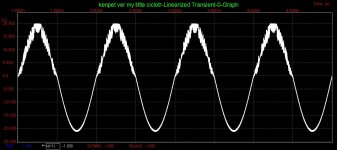
and look of sinewave close from clipping,
upper part oscillates strong
but lower soft...
Attachments
I got to think about this...
Problem is LTP transistors dip into shut-off at high frequency, near rolloff.
Probably because in/out error seen at the comparator becomes too great.
Increasing output bias into pure Class A cures it, but not fix I am wanting.
I am not seeing any big problem your shottky .model, it changes quiescent
slightly, but easy to bring back into alignment. I have 12R where I previously
drew 33R, and 12R straight to ground on the base of the cascode transistor.
No longer driven to follow output and provide equal LTP collector voltages,
but still provides for equal LTP collector dissipation.
Mind you: Only seeing problems at 96KHz and up, 48K and down all look OK.
And only at signal levels near the boundary of true clipping. But I don't think
we should be cutting any transistors off at any frequency considered to be
"inside the envelope".
Last edited:
- Home
- Amplifiers
- Solid State
- ♫♪ My little cheap Circlophone© ♫♪