Just need to aquire the 1.5nF and 27pF capacitors and I will be connecting power.
For the hell of it, I created a zip archive containing the final PCB gerbers, the builder's guide Elvee posted in text format, and the schematic:
http://dl.dropbox.com/u/5430178/circlophone/Circlophone Complete Files.zip
For the hell of it, I created a zip archive containing the final PCB gerbers, the builder's guide Elvee posted in text format, and the schematic:
http://dl.dropbox.com/u/5430178/circlophone/Circlophone Complete Files.zip
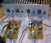
Elvee, I have one channel of the Circlophone up and running. Using a crappy test speaker so cannot comment on sound quality.
This is the setup:
http://dl.dropbox.com/u/5430178/project pics/Circlophone/3TESTING.jpg
http://dl.dropbox.com/u/5430178/project pics/Circlophone/4TESTING.jpg
I am using the MJW21196 as output transistors, and 2SB649 as drivers.
I have C11 (10nF) installed. I am using 270pF polystyrene as both C5 (input low pass) and C12 (the 180-820pF). For R8, R24, and R11 I am using 1.2R resistors for testing because I didn't have 1R. All other values are standard.
At first I had an electrolytic capacitor on the output to protect speaker in case of DC. After verifying offset stability I removed it. I also had 120R on the supply rails. After testing that it worked I removed those.
I had a scope (not the best -- a handheld digital DMM/Oscilloscope) on the output to check for oscillation. Before I connected power, I had extremely low level couple mV of 10-12MHz on the output, so when I did connect power and it was still this low level I am assuming this is just environmental noise. We have several LCD, Plasma televisions running at all times here where I am testing among other things.
For the supply I just rigged something up real quick. an 18-0-18 (DC) supply feeding only 2000uF of filtering going straight to the amp.
Playing music through it at low levels sounds good with the test speaker (beyond crappy). The heatsink, however, after a couple minutes to 10 minutes will get hot. I can hold my hand on it fine but it is uncomfortable. Not really painful, but not far from it.
I am wondering if this may be a problem. I think the heatsink is of decent size, as you can see in the picture. Could it be because I am using an incorrect suppy, or because I am using 1.2R instead of 1R for R8, 11, 24?
If so, then all else is fine, and we have a working channel.
Thanks.
Elvee, I have one channel of the Circlophone up and running. Using a crappy test speaker so cannot comment on sound quality.
This is the setup:
http://dl.dropbox.com/u/5430178/project pics/Circlophone/3TESTING.jpg
http://dl.dropbox.com/u/5430178/project pics/Circlophone/4TESTING.jpg
I am using the MJW21196 as output transistors, and 2SB649 as drivers.
I have C11 (10nF) installed. I am using 270pF polystyrene as both C5 (input low pass) and C12 (the 180-820pF). For R8, R24, and R11 I am using 1.2R resistors for testing because I didn't have 1R. All other values are standard.
At first I had an electrolytic capacitor on the output to protect speaker in case of DC. After verifying offset stability I removed it. I also had 120R on the supply rails. After testing that it worked I removed those.
I had a scope (not the best -- a handheld digital DMM/Oscilloscope) on the output to check for oscillation. Before I connected power, I had extremely low level couple mV of 10-12MHz on the output, so when I did connect power and it was still this low level I am assuming this is just environmental noise. We have several LCD, Plasma televisions running at all times here where I am testing among other things.
For the supply I just rigged something up real quick. an 18-0-18 (DC) supply feeding only 2000uF of filtering going straight to the amp.
Playing music through it at low levels sounds good with the test speaker (beyond crappy). The heatsink, however, after a couple minutes to 10 minutes will get hot. I can hold my hand on it fine but it is uncomfortable. Not really painful, but not far from it.
I am wondering if this may be a problem. I think the heatsink is of decent size, as you can see in the picture. Could it be because I am using an incorrect suppy, or because I am using 1.2R instead of 1R for R8, 11, 24?
If so, then all else is fine, and we have a working channel.
Thanks.
Additional information: the positive rail has 2.42A of current flowing through it

But music plays fine. Even sounds okay.
OOPS! Looks like I left R14 out completely. I'm guessing that doing so is not such a good idea... hah
Will report back.
OK. Installed R14 and now everything is good! ~140mA of draw on +V rail (18V). Sounds a hell of a lot better as well. Heatsink stays cool, time to let it run for an extended period.
Will report back.
OK. Installed R14 and now everything is good! ~140mA of draw on +V rail (18V). Sounds a hell of a lot better as well. Heatsink stays cool, time to let it run for an extended period.
Last edited:
Well, I've been playing it for a few hours continuous at low-ish levels at work, watching the scope on output looking for oscillation. Every now and then I see a waveform pop up, anywhere from 4-12MHz, about 20mVpp. It disappears after a few ms or so. Barely notice it pop up n leave. With amp switched off, and power drained from capacitors i.e. dead circuit, I still see that intermittent waveform. So, I conclude this is noise or coming from something else completely.
Letting this channel run and listening to some select songs, I can say it sounds very good. I hooked up a better test speaker as well. Very musical, and the highs are crisp and liquid. Crystal clear.
Time to get the rest of my work done so I can get the other pcb done and listen in stereo.
Also, I am still using the small test supply with crappy filtering and bypassing. So, I expect another improvement in sound once I get a proper supply connected.
One more thing to add: The amp is absolutely dead as a rock silent with no signal. Ear crammed up to tweeter or woofer and I can perceive nothing.
I'm back
Your amp looks OK.
140mA of Iq is marginally low, compared to my own prototypes and the expected spread of 150 to 250mA, but it still sufficient, nothing to worry about.
I recommend you make a squarewave test, this will immediately highlight any stability issue and will let you know wether the compensation caps are adequate or not.
Here is the confirmation of what I said earlier, and also of the versatility of the Circlophone's topology:
I simply dropped two NMOS in place of the darlingtons, in the Ndarlington version, and it worked exactly as expected.
The only things that required adaptation are the G-S resistors that have been increased to 390ohm.
Also, the lower clipping value predicted on the positive side is observed: the clipping occurs ~5V below the positive rail.
If the input voltage is reduced to just under the clipping, the behavior becomes almost identical to that of the BJT version: the THD is a bit higher, probably because of the lower transconductance of the MOS compared to the bipolars.
The bias servo too works in an identical manner.
A reminder:
all this is simulation, and nothing has been built yet.
But I will come up with a version using the same trick as the CircloMOS, build it, and launch a dedicated thread when it's mature and working well enough.
Here is this idea in sim.
The threshold of the MOSfets is cancelled by a memory capacitor, just as in the CircloMOS.
For simulation purposes, the capacitors have been replaced by voltage sources, V4 and V5, to avoid initial conditions issues.
The circuit does work, and the output clipping is now symetrical, but the linearity is disappointing: there is a ten-fold increase in the THD compared to other versions.
For this reason, I will not go further into this direction and I won't build a physical prototype.
Attachments
I'm back
Your amp looks OK.
140mA of Iq is marginally low, compared to my own prototypes and the expected spread of 150 to 250mA, but it still sufficient, nothing to worry about.
I recommend you make a squarewave test, this will immediately highlight any stability issue and will let you know wether the compensation caps are adequate or not.
You think it is just because of lower testing supply voltages? Also to note I used BC556/546 all in "C" suffix. Input pair is matched.
Unfortunately, Elvee, I do not know how I can do a squarewave test. I do not have a function generator. I have an oscilloscope though. Is there anything you would like me to do with that?
I have almost finished the second channel PCB. Soon I will be listening in stereo to give it a much better evaluation. So far, though, I am thoroughly enjoying it! It makes mainstream music enjoyable! Quite musical, and I find my self catching and understanding perfectly words in a song that I could not understand before. The midrange and high end is spectacular, yet I cannot comment on the bass (I am still using test speakers).
Could be the C suffix, I mainly used unsorted ones, without suffix.You think it is just because of lower testing supply voltages? Also to note I used BC556/546 all in "C" suffix. Input pair is matched.
Anyway, 140mA is large enough for the circuit to operate properly, nothing to worry about.
If you're happy with the sonics, and the amplifier looks well behaved, that's sufficient.Unfortunately, Elvee, I do not know how I can do a squarewave test. I do not have a function generator. I have an oscilloscope though. Is there anything you would like me to do with that?
But more generally, squarewaves are a useful tool to quickly uncover hidden issues, like marginal stability, insufficient internal bias currents, etc.
The squarewave behavior has little relation with the sonic performances, but it highlights any weakness in the design, like poor decoupling or compensation, inadequate wiring, unsuitable Zobel, etc.
You don't need a full feature function generator: for a buck or two, you can improvise an excellent generator on a scrap of veroboard, with a CMOS oscillator, see an example below
Looks promising.I have almost finished the second channel PCB. Soon I will be listening in stereo to give it a much better evaluation. So far, though, I am thoroughly enjoying it! It makes mainstream music enjoyable! Quite musical, and I find my self catching and understanding perfectly words in a song that I could not understand before. The midrange and high end is spectacular, yet I cannot comment on the bass (I am still using test speakers).
Attachments
Could be the C suffix, I mainly used unsorted ones, without suffix.
Anyway, 140mA is large enough for the circuit to operate properly, nothing to worry about.
If you're happy with the sonics, and the amplifier looks well behaved, that's sufficient.
But more generally, squarewaves are a useful tool to quickly uncover hidden issues, like marginal stability, insufficient internal bias currents, etc.
The squarewave behavior has little relation with the sonic performances, but it highlights any weakness in the design, like poor decoupling or compensation, inadequate wiring, unsuitable Zobel, etc.
You don't need a full feature function generator: for a buck or two, you can improvise an excellent generator on a scrap of veroboard, with a CMOS oscillator, see an example below
Looks promising.
Undoubtedly, that little tool will come in handy many times in the future, so I will have to build one when I can.
Thanks.
hello people,
nice to see a functioning amplifier
I'm currently in development a similar power amplifier. I do not know if you've noticed it(sub4668).
Nice circuit. The bandwidth and slew-rate must be impressive with the individual P-P drivers for each MOS.
Something isn't clear for me: why did you include a single cascode transistor, Q8?
Q5 sees a large static voltage, but the dynamic excursion is tiny.
On the other hand, Q4 sees the full output swing (a little more in fact).
I would think it would benefit more from the cascoding.
I would also be concerned about thermal stability. I see no obvious control or compensation mechanisms.
It would be a good idea to perform a thermal analysis in LTspice before you run the risk of frying real transistors.
Topologies like ours (same sex OP transistors) are inherently superior in this respect to more conventional complementary topologies.One of my fears is the switching on.
On your amplifiers, a strong turn-on is caused at the output?
In a classic complementary amplifier having an active VAS loaded by a passive CCS (or a bootstrapped resistor), the CCS becomes active before the VAS (or more rarely the opposite) when the amplifier "wakes up", causing a positive thump at the output, followed by negative "aftershock", when the charge accumulated by the capacitor in the NFB network is restored.
In principle, the overall NFB should minimize this effect, but if the amplification chain isn't fully active yet, the thump remains.
In principle, fully symetrical complementary designs should adress this problem, but the symetry of complements is mostly an illusion, and the small diffferences between the positive and negative sides is sufficient to cause a large thump, because of the high current gain of the output stage.
On the other hand, circlo designs like yours and mine rely on a horizontal symetry rather than a vertical one, and thus have both halves waking up with almost perfect synchronism, minimizing unwanted output excursions at power-up.
These excursions are further controlled by the NFB as soon as it becomes active, and in the case of the Circlophone, the bias servo also helps control the behaviour of OP transistors, even at an early stage of the powering up.
Note that even if the PA is silent at power up, the preamplifier might still inject its own disturbances.
The cascode at this point is easy to implement and ensures the same quiescent current performance....why did you include a single cascode transistor, Q8?
Q5 sees a large static voltage, but the dynamic excursion is tiny.
On the other hand, Q4 sees the full output swing (a little more in fact).
I would think it would benefit more from the cascoding.
Q4 have only to sweat at very high levels. There would be too complicated to add a cascode.
Q10 is thermally connected to the MOSFET.I see no obvious control or compensation mechanisms.
My amps are usually symmetrical and turn on all soft. So my concern.In principle, fully symetrical complementary designs should adress this problem
Thank you for your explanation. I hope the amp will works fineOn the other hand, circlo designs like yours and mine rely on a horizontal symetry rather than a vertical one, and thus have both halves waking up with almost perfect synchronism, minimizing unwanted output excursions at power-up.
These excursions are further controlled by the NFB as soon as it becomes active, and in the case of the Circlophone, the bias servo also helps control the behaviour of OP transistors, even at an early stage of the powering up.
Both channels up and running. More to update later.
I have some parts to change on the first channel. Used different type capacitors on second channel in some places and I feel it sounds better. I want both channels to be as similar as possible. Have the same 140mA draw on the positive 18V rail. No oscillations at all with these 4MHz MJW21196's.
I still can't get over how "fast" the amp sounds. When snare hits for example, it has great attack and just seems very fast for lack of better words. Dynamic.
Is anybody else building? Oh well, at least I will enjoy mine for the moment. I think others need to build. I'm loving the sound so far. It's delicious!
Soon I will have it on the proper supplies (still only using 2,000uF/rail, +-18V), and the proper speakers.
Attachments
Soon I will have it on the proper supplies (still only using 2,000uF/rail, +-18V), and the proper speakers.
With the MJW21196's and the heatsink you use, you could very easily double the supply voltage.
You just need to increase R21 to 56 or 68K.
With the MJW21196's and the heatsink you use, you could very easily double the supply voltage.
You just need to increase R21 to 56 or 68K.
I was going to ask about foregoing the use of the regulator boards and just using about +-33V. So, which value would be better, 56 or 68K?
Thanks!
56K would be closer to the design goal for 2x33V, but it isn't that critical at all, and I made tests between 15V and 45V without modifying anything.
Not something I would recommend though, but it shows the tolerance of the circuit.
One thing I forgot to mention, if you use 33V supplies, the zeners should have a total voltage in that region: 2x15V or 16V, or 1x30V or 33V (1.3W for a single).
Not something I would recommend though, but it shows the tolerance of the circuit.
One thing I forgot to mention, if you use 33V supplies, the zeners should have a total voltage in that region: 2x15V or 16V, or 1x30V or 33V (1.3W for a single).
Some news:
I have tested (in sim) the idea of replacing the zeners with a resistor.
The result is disappointing: the change in linearity is insignificant, and for the worst.
It looked like a good idea in theory, but it doesn't deliver, and if there is no improvement in sim it's probably not worth testing in reality.
In addition, it would probably upset the compensation and degrade the dynamic performances.
Replace the two Zeners with one NPN in cascode?
I mean w. base referenced to output...
Q6 already rides one emitter (Q11) below the output,
both Q5 & Q6 should then see same collector voltage.
56K would be closer to the design goal for 2x33V, but it isn't that critical at all, and I made tests between 15V and 45V without modifying anything.
Not something I would recommend though, but it shows the tolerance of the circuit.
One thing I forgot to mention, if you use 33V supplies, the zeners should have a total voltage in that region: 2x15V or 16V, or 1x30V or 33V (1.3W for a single).
Thanks.
- Home
- Amplifiers
- Solid State
- ♫♪ My little cheap Circlophone© ♫♪