Ok, How about this?
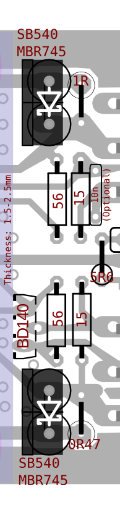
16mm diameter decoupling capacitors still possible if output transistors should solder from bottom of pcb which is optimum case for this layout. . . .
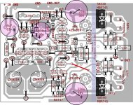
The phase inverter area looks good except that the resistors are pressed together, which would make them hot. Resistor body should go closest to transistor base, so maybe all you'd need to do is invert the photo of the 1k2 resistors and give them a couple more millimeters farther apart spacing. . . although leaning the 1k2 away from each other is an alternative option.
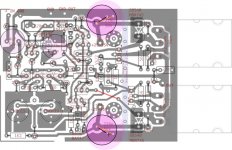
You might look for opportunities to make same/similar trace lengths for both 2n3019 and/or you can slightly thicken the traces that are longer to make them "virtually shorter" length.
The traces, especially collector, for 2n3019 could be thickened as that would surely help cool the devices.
The 220u caps shouldn't go between two heatsinks since they would cook for sure. It seems that a better spot for the 220u is right at the areas marked +VS and -VS since there's nothing especially hot right there and they wouldn't block airflow if you put them there. So you might want to revert that part so that it is very similar to post 712, except with the 220u about 7mm farther left than shown in post 712.
Last edited:
I attached MBR's to heatsink. MBR datasheet says there is no flaw until 110℃ ambient temperature. I didn't measure BD's sink bar temperature but it seemed to me quite gentle. IF 10nf optional cap choosed such kind of multilayer small one (AVX for example) it shouldn't be other possible flaw.
If it seemed ok for you too, i think we made something for real this time.
Thanks.
If it seemed ok for you too, i think we made something for real this time.
Thanks.
Attachments
Wow, that board should run much cooler, and it probably won't need a fan if the enclosure has good input and output vents.
The 2n3019 are supposed to be identical twins as closely as possible, so. . .
At the lower left corner, the traces of the left side 2n3019 need to be diagonalized to match (similar to) the traces of the right side 2n3019. The left side 1k2 needs to be set closer to the corner so as to more closely resemble the right side 1k2.
Actually I had intended only slightly thicker traces, but your minimum etch style should work nicely although more tightly fitted, thicker, ground shield at the lower left could be good since the point of minimum etch styles is having as much ground shield as possible.
The BD140 driver area is looking much cooler. The vias for ventilation (anti-heat-pooling) don't need to be copper lined. I actually wasn't proposing any major changes to the driver area. However, your new version is looking much cooler. Collector for the upper BD140 has a very long trace and some of that trace could be made "slightly" thicker, if you like.
Last edited:
I'm trying to learn simulating with LTspice. I don't know how to read Phase Degree results and determine amplifier's stability margin or such.
Attached pictures are error logs of CFP Circlophone in Darlington and actual output configurations with BC550C/BC560C input transistors. Values of phase degrees very differs despite their very reasonable THD values. So, can you give a short brief or recommend me a document which clarifying to these numbers for easy understanding?
Attached pictures are error logs of CFP Circlophone in Darlington and actual output configurations with BC550C/BC560C input transistors. Values of phase degrees very differs despite their very reasonable THD values. So, can you give a short brief or recommend me a document which clarifying to these numbers for easy understanding?
Attachments
Last edited:
However, because the board at post #712 has been tested, I've generated a "minimal modifications" example, allowing room for heatsink at phase inverter and driver. When a board has been tested, then one possible good approach is to make the least changes possible.
Since minimized changes was my intention, here's an example of it.
Larger driver heatsink and vent drillings are desired, but not yet shown, and it seems that the 5a schottky need to be brought 2mm closer to each other, so as to allow slightly more room for the 220u caps. Again, only very slight modifications here:
Attachments
You are looking at the wrong place: stability has nothing to do with the distortion.I'm trying to learn simulating with LTspice. I don't know how to read Phase Degree results and determine amplifier's stability margin or such.
Attached pictures are error logs of CFP Circlophone in Darlington and actual output configurations with BC550C/BC560C input transistors. Values of phase degrees very differs despite their very reasonable THD values. So, can you give a short brief or recommend me a document which clarifying to these numbers for easy understanding?
You have to make an AC analysis, not a transient, and insert the stimulus source at some convenient point of the loop.
The subject and methods have been discussed a number of times, do a search on the forum.
Here is already some information:
http://www.diyaudio.com/forums/software-tools/101810-spice-simulation-13.html#post1213665
I think Keantoken has also given some explanation somewhere, perhaps in a wiki
However, because the board at post #712 has been tested, I've generated a "minimal modifications" example, allowing room for heatsink at phase inverter and driver. When a board has been tested, then one possible good approach is to make the least changes possible.
Since minimized changes was my intention, here's an example of it.
Larger driver heatsink and vent drillings are desired, but not yet shown, and it seems that the 5a schottky need to be brought 2mm closer to each other, so as to allow slightly more room for the 220u caps. Again, only very slight modifications here:
The #712 was tested for to sure input pair alignment and compensation values are right for very high gain transistors like BC550C/BC560C. It is the most important part in CFP version and I didn't altered there.
I think we surpassed all previous ones with latest layout in terms of heatsink, decoupling caps and power schottky placement. The bottleneck related with decoupling capacitors is left side circuitry and heatsink axis. Placement of power schottkies don't help too much there. Current layout seemed to me optimum which allowing 16mm caps if shorter heatsink bar used.
I sight you feel uncomfortably with servo side. Since those transistors weren't placed as symmetrically, you have to adapt the things asymmetrically as well, like what I did with 1K2 resistors. If you follow shorter trace of base pins and 1K2's bodies, you'll see they are equal. As similar with upper transistors.
I willingly adapt your highly modified version take ons then I'm going to to build one. This layout should be shared as Original version as well, if I could do it in short.
You are looking at the wrong place: stability has nothing to do with the distortion.
You have to make an AC analysis, not a transient, and insert the stimulus source at some convenient point of the loop.
The subject and methods have been discussed a number of times, do a search on the forum.
Here is already some information:
http://www.diyaudio.com/forums/software-tools/101810-spice-simulation-13.html#post1213665
I think Keantoken has also given some explanation somewhere, perhaps in a wiki
Thank you Elvee, this explains why there is a source somewhere between loop in your previous schematics. This information fair enough to know where to begin.
Last edited:
If you insert the source between a low impedance output and a high impedance input, you can dispense with the complete matrix calculation (in practice, at least).I
Thank you Elvee, this explains why there is a source somewhere between loop in your previous schematics. This information fair enough to know where to begin.
You simply have to display the ratio of the voltages of the source's nodes.
Remember that the analysis will be performed for the initial conditions: if you have a sine input as is customary, you will see the result for the quiescent conditions, because sin 0° = 0.
If you want to check the behavior at some output voltage/current level different than 0, you have either to add a phase shift, or change the source for a DC one with the correct voltage.
But then, be sure to remove the DC blocking capacitors, otherwise the initial OP calculation will eliminate it
Finally:
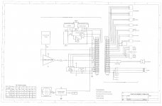
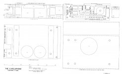
The Gerber file, a SLD and a mechanical drawing of ELVEE's post #369
The Gerber shows 5 boards: the amp (no kiddin!) which is a DIN standard 100x1600 mm board, the back-plane for it, a fuse-holder board and 10-LED "VU" meter board (these 2 fit in between the fins of the heatsink. The last board (not tested) is a constant current source to replace R21. In simulation of the current shows a +/- 2% deviation, 30 to 120VDC, of preset current
The Circlophone is that of post #1. I added a preamp with features to suit my own needs. These parts can be omitted as this C has a strappable input connection
Cheers, E
Attachments
Finally:
The Gerber file, a SLD and a mechanical drawing of ELVEE's post #369
The Gerber shows 5 boards: the amp (no kiddin!) which is a DIN standard 100x1600 mm board, the back-plane for it, a fuse-holder board and 10-LED "VU" meter board (these 2 fit in between the fins of the heatsink. The last board (not tested) is a constant current source to replace R21. In simulation of the current shows a +/- 2% deviation, 30 to 120VDC, of preset current
The Circlophone is that of post #1. I added a preamp with features to suit my own needs. These parts can be omitted as this C has a strappable input connection
Cheers, E

Thanks for the great work, I am sure this version will meet the needs of those wanting the "professional" version of the Circlophone.
On purpose?New challenge if you dare...
Parallel Circlophones with different rails, or one with rail commutation?
Okay, more seriously, I think you'd need to add the two transistors that allow for variable voltage source. Unfortunately, when I added Q14, I had that head in a vise sensation from bad quality HF output. The noise, or at least the discomfort, is about the same as omitting the cap from the feedback resistor. Anyway, the rather powerful distortion was about that same frequencies, just barely above the audio band, and surely not far enough. Ouch. So, that problem needs attacked before using variable voltage source (or at least before actually using Q14). There's not enough Tylenol for that much distortion.
Last edited:
Another thing in my mind is could we benefit CFP version as a phono-stage-less amp, but without a RIAA equalization. If it is applicable with adding an active or passive RIAA stage, that would be great deal for analogue users those who generally fighting with noise issues at preamp stages.
This will be very interesting study to see RIAA equalization achievement at output of Circlophone CFP with LTSpice.
This will be very interesting study to see RIAA equalization achievement at output of Circlophone CFP with LTSpice.
I was wondering how to work out the zener setting for the regulator (minimum required voltage drop), based on predicted voltage drop from rectifier (KBPC2506 per each secondary) and documented voltage drop from transformer and the possibility of a 4 ohm speaker load (or the similar load of a rather difficult 8 ohm speaker).
My 400va transformer datasheet gives these figures.
No load: 26v (secondaries in parallel)
7a load: 25.5v (secondaries in parallel)
10a load: 25v (secondaries in parallel)
17a load: 24v (secondaries in parallel)
Some people would choose a half price transformer, like this 200va:
No load: 28v (secondaries in parallel)
6a load: 26v (secondaries in parallel)
9a load: 25.5v (secondaries in parallel)
Apparently, if you buy a transformer based on lowest voltage drop figures, that results in a very huge transformer. It is 13cm across, 6cm tall and very heavy. I've listed two transformers in order to get 2 data points for extrapolation, so that you won't have to answer the same question for every transformer variety.
I'm assuming that the answer for monobloc (running with the 200va example above) is something like the ~6a pulldown figure (26v), multiply by 1.45? for capacitor rectification, subtract 2.5 for margin and then the zener figure is (15+20) 35v? Correct?
I'm also assuming that a stereo amp (running with the 400va example above) is going to be using 33v zeners at the regulator boards?
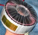
Gratuitous transformer overdo photo:")
My 400va transformer datasheet gives these figures.
No load: 26v (secondaries in parallel)
7a load: 25.5v (secondaries in parallel)
10a load: 25v (secondaries in parallel)
17a load: 24v (secondaries in parallel)
Some people would choose a half price transformer, like this 200va:
No load: 28v (secondaries in parallel)
6a load: 26v (secondaries in parallel)
9a load: 25.5v (secondaries in parallel)
Apparently, if you buy a transformer based on lowest voltage drop figures, that results in a very huge transformer. It is 13cm across, 6cm tall and very heavy. I've listed two transformers in order to get 2 data points for extrapolation, so that you won't have to answer the same question for every transformer variety.
I'm assuming that the answer for monobloc (running with the 200va example above) is something like the ~6a pulldown figure (26v), multiply by 1.45? for capacitor rectification, subtract 2.5 for margin and then the zener figure is (15+20) 35v? Correct?
I'm also assuming that a stereo amp (running with the 400va example above) is going to be using 33v zeners at the regulator boards?
Gratuitous transformer overdo photo:
Attachments
On purpose?
Okay, more seriously, I think you'd need to add the two transistors that allow for variable voltage source. Unfortunately, when I added Q14, I had that head in a vise sensation from bad quality HF output. The noise, or at least the discomfort, is about the same as omitting the cap from the feedback resistor. Anyway, the rather powerful distortion was about that same frequencies, just barely above the audio band, and surely not far enough. Ouch. So, that problem needs attacked before using variable voltage source (or at least before actually using Q14). There's not enough Tylenol for that much distortion.
Use of Q14 depends upon moving compensation to the new collector.
With Zeners: It matters very little which end gets comp'd. Diode side
is pegged dynamically to the upper rail at both ends of the diode stack.
You do get at least half differential compensation between the pegged
collector, and the other that swings with output. But, half is enough...
With Q14: If you comp at the old place, cascode block compensation.
In cascode, both collectors of the second pair will appear to swing in
unison, thus is nothing happening in the comp network... No comp is
asking for problems, and might be the "vice" you hear.
Last edited:
That would create a number of serious problems: you would have to insert a volume control in the very low level circuitry, and that would be difficult to achieve cleanly and without adding noise.Another thing in my mind is could we benefit CFP version as a phono-stage-less amp, but without a RIAA equalization. If it is applicable with adding an active or passive RIAA stage, that would be great deal for analogue users those who generally fighting with noise issues at preamp stages.
This will be very interesting study to see RIAA equalization achievement at output of Circlophone CFP with LTSpice.
Placing the RIAA eq at the output would be incredibly wasteful, with a colossal loss of dynamic and power.
Not a good idea IMHO
- Home
- Amplifiers
- Solid State
- ♫♪ My little cheap Circlophone© ♫♪