Feedback shunt diodesThe diodes only role is as a safeguard, in case something goes wrong with the supplies powering sequence for example, to avoid excessive charge building up on C3. Doubling them means the output voltage during unexpected transient conditions could practically reach the supply rails, which is undesirable and will almost cancel their usefulness.
Thanks for the specs on that. I will fix the schematic so that next time you see it the feedback shunt diodes are like post 1. That whole scenario of partial diode switch on is only a concern if someone oversizes the input cap a lot, or undersizes the feedback shunt cap a lot in which case the voltage could peak up at knee voltage (albeit almost never full switch on, yet still partially active). But in this case your D10, D11, diodes actually minimize bass distortion in trade for a temporary and extremely slight bit of raspy during each momentary occurrence. Just using the right size input and feedback shunt caps seems more appropriate than decreasing the protection, aka the right fix instead of the wrong fix. Sorry for my error there. Thanks for explaining the D10, D11 function.
To avoid very severe spikes damaging the B-E junctions of Q4 and Q3, one could add a pair of back to back diodes between the bases.
This will not actually clip anything, but it will not impact the linearity, and it will make the input practically bullet-proof.
Each base already has a resistor to ground. I would cross the diodes
not directly from base to base, but from base to a few ohms down into
one or other of the fore-mentioned resistors.
For the same reason we would never bridge a cap directly from base to
base to kill high input frequencies. It provokes a parasitic oscillation...
A little less than unity in the base to base shunting prevents accidental
latch or instability if any overtone comes back to us slightly over unity.
If you make one base to GND resistor a pot, you can also adjust the
diode threshold with this pot to a soft clip the input just before hard
clipping is tripped by error from the output. The same pair of diodes
can perform both input and output, soft and hard clip management.
See #564 for drawing...
Last edited:
Each base already has a resistor to ground. I would cross the diodes not directly from base to base, but from base to a few ohms down into one or other of the fore-mentioned resistors.
For the same reason we would never bridge a cap directly from base to
base to kill high input frequencies. It provokes a parasitic oscillation...
A little less than unity in the base to base shunting prevents accidental
latch or instability if any overtone comes back to us slightly over unity.
If you make one base to GND resistor a pot, you can also adjust the
diode threshold with this pot to a soft clip the input just before hard
clipping is tripped by error from the output. The same pair of diodes
can perform both input and output, soft and hard clip management.
See #564 for drawing...
That's really neat and tidy. I would love to test drive it, but do not know how. Could you illustrate it with a Circlophone schematic so I could identify how to install it?
R16 is 470, so just cut my resistor values (based on 1K base to GND) in half...
You might want to cover more range than 50ohms on the pot if you use other
than 24V rails, I'm not sure where the sweet spot for your tweakage will be.
The whole thing (R16 - Circlophone #1) could be a 20 turn pot I suppose?
Though much the rage where you might tap input pair base to base diodes
into this pot's wiper instead, would be covered in one turn or less.
If you adjust all the way to the base end, it could oscillate or latch.
If you adjust all the way to GND end, it provides no management
for the case of output clipping (still might turn off an input transistor).
You gonna be somewhere in the middle, and probably closer to the
base than GND to have both these problems solved...
----
You would not use my hard clip diode bridge from gate to gate, as it would
do less than nothing for Elvee's 2n3019 BJTs. His did not suffer instability
in hard clip anyway, so those extra diodes doubly not needed for nuthin'.
Also don't use cap (c5 my schematic) in Elvee's circlophone, not applicable...
----
It boils down to one resistor (R16 sch#1) to be substitued by an equal or
near value (maybe 500R) pot, and two silicon diodes of opposite orientation
wired in parallel. One end of this diode pair connected to (Q4 sch#1)'s base,
and the other to the wiper of this new pot R16.
7K8 shunted across 500R (the long way of course) would be same as 470.
Last edited:
From the base of the + input, opposing parallel diodes connect to the wiper of a potentiometer that has been used as feedback shunt resistor of the - input. Correct? I don't actually have a 500R pot handy, so this awaits parts.. . .It boils down to one resistor (R16 sch#1) to be substituted by an equal or near value (maybe 500R) pot, and two silicon diodes of opposite orientation wired in parallel. One end of this diode pair connected to (Q4 sch#1)'s base, and the other to the wiper of this new pot R16. . .If you adjust all the way to the base end, it could oscillate or latch. If you adjust all the way to GND end, it provides no management for the case of output clipping (still might turn off an input transistor). You gonna be somewhere in the middle, and probably closer to the base than GND to have both these problems solved. . .
There was a few questions.
Does the very slight internal capacitance of these added parts make any significant reduction to the capacity for gain?
Is there some way to calculate near match (near miss?) resistor values based on rail voltage?
-------------
As promised, here is a schematic outfitted with a convenience chart to match up parts with potential (and your resistor divider could be added). Engineers won't need that chart, but constructors might like it. Notice the heavily de-rated output devices, could exceed safe operating area if pushed to somewhat audible clipping. For example, the reasonably clean 4 ohm power output is almost the same as the 8 ohm clipped output; however, the explosion happens if 4 ohms and clipping. At some point it would be useful to "ride the brakes" rather than ever larger output devices at ever lower voltage. Or, as an alternative, we could try some of those massive brick looking IGBT's that Fuji makes for RV generators.
") However, I think that your two diodes and resistor divider is more reasonable. I would like to implement that without a trimmer dial; however, I'd need some example resistor figures (at least 2 data points) for success.
However, I think that your two diodes and resistor divider is more reasonable. I would like to implement that without a trimmer dial; however, I'd need some example resistor figures (at least 2 data points) for success.Attachments
In TO220: BDT85
SOT93: BDV95
I visited some local suppliers today for able to find some Philips power bjt's. Someone offered me a BD245C which insisted as a genuine part.
I discuss and upload a photo here.
Last edited:
As the amount of brand names is different than the amount of factories, I don't know how to guarantee the lineage of any part except for traveling to the factory and knocking on the door. Generally, we trust vendors to do that task. The part is similar to Philips 3055T, except that BD245C has safer voltage tolerances. I'm glad that the part you chose can do a better job in outlasting a power surge and won't mysteriously quit when the lights happen to blink. It might be good to also review the voltage tolerances at Q12, Q13 and consider if they will outlast voltage fluctuations.I visited some local suppliers today for able to find some Philips power bjt's. Someone offered me a BD245C which insisted as a genuine part.
I'm not completely certain, but I think that Circlophone has a local feedback at output devices so that variety at that point doesn't impact sound quality. It seems that you have a very nice output device there for use with 8 ohm speakers. And, I eagerly await your description of the performance of your Dutch Circlophone project.
It is really great to be able to run Circlophone from a variable voltage source, such as for an efficiency application. But, that sort is probably a project for later.Here are two further possibilities for replacing R21: a plain vanilla 1 transistor CCs, and an improved one with a zener.
What I actually need is to verify that the R21 resistor values on my constructor's chart are correct for the given voltage. This version of the table has been streamlined and there are some alternate parts listed as attractively as possible. I'd like suggestions on making this look even better and see if the parts are optimal selections.
Although it seems that parts availability problems have been defeated (awaiting your approval of the parts listing), the remaining availability problem for some, will be circuit boards. Is there good news on available circuit boards?
And some other notes, about options:
Since the clip performance of Circlophone is so very clean, a soft clip device isn't necessary although the Circlophone specific hard clip detector or any way to block accidental hard clip is probably of some benefit since it can work faster than I can run. . . to the volume knob, the amplifier is Very dynamic and so volume differences between tracks can be dramatic. If I was successful with the constructor's chart added to your schematic, the possible explosion is at the woofer, not the output device. By strong derating, I have attempted to remove the necessity of an added circuit. Could you give it a look and see if the derating is satisfactory?
On my own Circlophone, not shown on the schematic, I've removed C5 and instead put back to back simple zener protector (3.4v plus forward drop for about 4v blocker that is also capacitive) parallel with 10K input load, R20 (to resist computer startup and "resume" surges) and the odd behavior is gone, the frequency response leveled out and the performance is still fantastic. Perhaps there is some refined version of this that you might find suitable?
I am unclear as to whether the project is supposed to be a power amp or integrated amp, but I desire integrated amp for intelligibly loud output despite weak modern sources. For not having to use high gain at the power amp and for allowing a wider variety of sources and wider variety of source impedance, it seems possibly useful to have a jfet gain stage at input. What do you think of that? Can it be added?
Attachments
Last edited:
Daniel, good to see someone here who is a good listener that can define a violin's brand while listening an amp and also can do something useful on an electronic circuit to satisfy own needs.
My source is a computer too and I don't turn on my computer while my (any of) amplifier is running. That "bump" is not seeming to me harmful but sometimes became stressful.
My source is a computer too and I don't turn on my computer while my (any of) amplifier is running. That "bump" is not seeming to me harmful but sometimes became stressful.
I doubt it very much: the BD245 has never been on any official catalogue from Philips, and the style of case and marking doesn't fit either: looks more like something of extreme-oriental origin.I visited some local suppliers today for able to find some Philips power bjt's. Someone offered me a BD245C which insisted as a genuine part.
That's OK, the value in KΩ ~= 0.9 times the total AC supply.What I actually need is to verify that the R21 resistor values on my constructor's chart are correct for the given voltage. This version of the table has been streamlined and there are some alternate parts listed as attractively as possible. I'd like suggestions on making this look even better and see if the parts are optimal selections.
I think Mickeymoose is ready to take subscriptions for the new version of PCB.Although it seems that parts availability problems have been defeated (awaiting your approval of the parts listing), the remaining availability problem for some, will be circuit boards. Is there good news on available circuit boards?
I can launch a specific thread for this.
The BUX20 is not a suitable choice: it is an old generation transistor, with anCould you give it a look and see if the derating is satisfactory?
SOA much more limited than the MJ's.
A jFET buffer can certainly be added, a gain stage is trickier.I am unclear as to whether the project is supposed to be a power amp or integrated amp, but I desire integrated amp for intelligibly loud output despite weak modern sources. For not having to use high gain at the power amp and for allowing a wider variety of sources and wider variety of source impedance, it seems possibly useful to have a jfet gain stage at input. What do you think of that? Can it be added?
It is preferable to increase the closed loop gain of the amplifier.
An alternative would be a darlington or CFP input pair. I'll think about it.
@terranigma Thanks man. I think that Elvee's Circlophone is very fun amplifier, so easily tunable and then there's the amazing dynamics. Have you tried optional gain settings? Aren't the dynamics just huge that way? I think it sounds a lot like a real concert.
@Ken Your soft clip device is amazing! Has anyone else tried it? Wow, enormous soundfield size boost! Although it doesn't seem to work as expected, I do really like it. Thank you!!!
@Ken Your soft clip device is amazing! Has anyone else tried it? Wow, enormous soundfield size boost! Although it doesn't seem to work as expected, I do really like it. Thank you!!!
@terranigma Thanks man. I think that Elvee's Circlophone is very fun amplifier, so easily tunable and then there's the amazing dynamics. Have you tried optional gain settings? Aren't the dynamics just huge that way? I think it sounds a lot like a real concert.
Agree Daniel, That's why circlophone became my prior diy occupation. Want to try different drivers? power transistors? bias servo transistors?.. no struggle to find any pnp/npn complementaries.. just read specs, put it if fits, then listen... This is really fun. Altering caps, pcbs even resistors is also fun. I didn't alter nfb resistor value yet but it is one of things in trial list also. Circlophone seemed to me a template of an ideally specified elegant amplifier rather than something immutable.
Last edited:
Other than expected in what way?
Acutance, with the dramatic high resolution, high fidelity benefits plus the unfortunate apparent frequency response caveats that can come with it if not precisely calibrated. It is a similar topic to anti-compensation, feed-forward, r-comp, and square wave test. The unfortunate part happens when the acutance halo size, aka duration, is set too large. If we can't dial it back, the feature is self defeating after leveling apparent response via the power circuit, in that two wrongs won't make a right. If we can shrink the halo size (reduce noise), aka decrease duration, then some mild power circuit tuning that does very little, can recoup the apparent frequency response. . . resulting in a very top class high fidelity amplifier.
Right now, the effect is a "toe over the line" into noise. Let's try to adjust this effect in some way.
In print the topic is that you must have a tighter focus to make a larger print, and the larger the print, the tighter focus you must have to avoid amplifying blur (falls apart is the print term for when amplifying the size causes suddenly too much blur). Magnifying the print size is amplification, as for example a 4 foot photo goes beyond the means of a 35mm negative. Precisely sized acutance removes the blur and makes a sharp overlarge print possible. The concept also works for audio. Of course it is more complex than that, but it is surprising that your simple soft clip device has some control over this necessary aspect of amplification.
Yes, you pushed the sharpen button quite well, but now we must set the gate size smaller so the edges aren't exaggerated. The amplitude seems perfect but the duration an overdo. How to adjust only that?
I missed something important yesterday: 1N5819 is not a suitable type for D7, it is a power diode with a very low Vf at low currents, and there is a very real risk it clips too early, fooling the bias servo into believing the current in Q10 is too low.there are some alternate parts listed as attractively as possible. I'd like suggestions on making this look even better and see if the parts are optimal selections.
Although it seems that parts availability problems have been defeated (awaiting your approval of the parts listing)
This will have disastrous consequences, as the servo will send the maximum current into both OP devices, destroying them in a matter of milliseconds.
Only signal schottky's should be used there, with a maximum current rating of 300mA or less.
I missed something important yesterday: 1N5819 is not a suitable type for D7, it is a power diode with a very low Vf at low currents, and there is a very real risk it clips too early, fooling the bias servo into believing the current in Q10 is too low.
This will have disastrous consequences, as the servo will send the maximum current into both OP devices, destroying them in a matter of milliseconds.
Only signal schottky's should be used there, with a maximum current rating of 300mA or less.
1N5819 starts at 0.12v (onsemi's most popular signal schottky)
That dodgy little thing will blow up my output devices? Oh no!
BAT86 starts at 0.12v (static resistant, Vishay and NXP)
BAT85 starts at 0.09v (low availability)
BAT83 starts at 0.09v (low availability)
That all seems possibly accident prone? Perhaps an ordinary 1n914 is a safer choice than a schottky? So, what part is the safest/best choice for D7? I don't know, but had to ask.
Last edited:
The 1N5819 is NOT a signal schottky, it is categorized as schottky rectifier.1N5819 starts at 0.12v (onsemi's most popular signal schottky)
Where do you see that diodes "start" somewhere? They have a logarithmic voltage/current characteristic.That dodgy little thing will blow up my output devices? Oh no!
BAT86 starts at 0.12v (static resistant, Vishay and NXP)
BAT85 starts at 0.09v (low availability)
BAT83 starts at 0.09v (low availability)
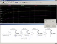
Here is a comparison between various types for a current swept between 0 and 3mA.
At 1.5mA, the Vf should not be lower than 250mV. The actual danger zone begins at 220mV.
Diodes like the BAT54 (300mA) just fit. The 1N5819 is completely on the wrong side of the fence
You should not try to second guess all the design decisions, there are excellent reasons for not using a 1N914, as there there are equally good reasons for not using power schottky'sThat all seems possibly accident prone? Perhaps an ordinary 1n914 is a safer choice than a schottky? So, what part is the safest/best choice for D7? I don't know, but had to ask.
Attachments
Well, I apologize. I didn't want to second guess or guess at all; however, the BAT diodes are in short supply except for BAT86, BAT85, BAT54 and a few similar. So, that topic is about parts availability and avoiding the hindrance of discontinuances or the expense of rarities. Also, BAT54, although highly available, the SMD part doesn't fit through hole board easily.You should not try to second guess all the design decisions, there are excellent reasons for not using a 1N914, as there there are equally good reasons for not using power schottky's
??? I could not make that work in all conditions, for all transformers, with all power supplies, in all locations, so I changed the constructor's chart to real DC measures because managing transformer variety was too far beyond the scope of a little chart.That's OK, the value in KΩ ~= 0.9 times the total AC supply.
How do I calculate R21 from DC? I've used your guidelines posted here: http://www.diyaudio.com/forums/solid-state/189599-my-little-cheap-circlophone-4.html#post2688812 for some of the examples and then attempted to extrapolate the rest.
So, here is the chart by itself (temporarily large), along with a new question of how much DC voltage can we use when specifically 8 ohm speakers?
Apparently a fun 75 watt version of the original has appeared with the MJ15015 being the higher voltage version of 2N3055. But, for some of the higher voltage selections I worry about overheating some of Circlophone's resistors. Which chart selections aren't suitable?
Attachments
Last edited:
Acutance, with the dramatic high resolution, high fidelity benefits plus the unfortunate apparent frequency response caveats that can come with it if not precisely calibrated. It is a similar topic to anti-compensation, feed-forward, r-comp, and square wave test. The unfortunate part happens when the acutance halo size, aka duration, is set too large. If we can't dial it back, the feature is self defeating after leveling apparent response via the power circuit, in that two wrongs won't make a right. If we can shrink the halo size (reduce noise), aka decrease duration, then some mild power circuit tuning that does very little, can recoup the apparent frequency response. . . resulting in a very top class high fidelity amplifier.
Right now, the effect is a "toe over the line" into noise. Let's try to adjust this effect in some way.
In print the topic is that you must have a tighter focus to make a larger print, and the larger the print, the tighter focus you must have to avoid amplifying blur (falls apart is the print term for when amplifying the size causes suddenly too much blur). Magnifying the print size is amplification, as for example a 4 foot photo goes beyond the means of a 35mm negative. Precisely sized acutance removes the blur and makes a sharp overlarge print possible. The concept also works for audio. Of course it is more complex than that, but it is surprising that your simple soft clip device has some control over this necessary aspect of amplification.
Yes, you pushed the sharpen button quite well, but now we must set the gate size smaller so the edges aren't exaggerated. The amplitude seems perfect but the duration an overdo. How to adjust only that?
Bizarre rant makes no sense whatsoever, stealing my stolen thunder...
---------
Its simple:
A soft clip is reversible. Information is distorted. No information is lost.
If you went to enough trouble, the original signal can be reconstructed.
Maybe our brains do some of this processing intuitively.
Hard clipping is irreversible. Information is smashed flat against a limit.
The limit can be voltage or current, quantization, or any other arbitrary.
We only guess what was destroyed where the information used to exist.
Not an attenuated hint remains to help us fill in the blank.
Even at similar THD, the latter distortion sounds a lot worse (to me).
When we wish to play music with a larger dynamic range than that fits
our amplifier, we have to make choices how best to handle impossible.
Else the default choice will be be made for us, probably to no good.
Last edited:
- Home
- Amplifiers
- Solid State
- ♫♪ My little cheap Circlophone© ♫♪