Some details here:
https://www.diyaudio.com/community/threads/my-little-cheap-circlophone-c.189599/post-2642853
https://www.diyaudio.com/community/threads/my-little-cheap-circlophone-c.189599/post-2681184
https://www.diyaudio.com/community/threads/my-little-cheap-circlophone-c.189599/post-2682260
There are probably additional explanatory posts, but I only explored the first 550 posts. With some patience, you can probably locate them. The builder's thread may also contain references
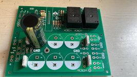
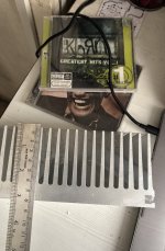
Progress on my boards, awaiting 215mm x 75mm x 75mm heatsink. After which the holes and tapping will need to be done (coming Saturday hopefully)
Also need to get 60 or 70 watt soldering iron since my old 25watt is not able to solder the power caps with the massive ground plains
Need to test the speaker protection section.
Funny thing along LM3886’s, MJL21194G, MJL21196’s it seems 5mm pitch MKP wima 4.7uf’s, Nichicon UES (Muse) are not there on Digikey, Element 14, RSComponents.
New dilemma now caps
Note: pcb’s needs a cleaning
Attachments
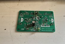
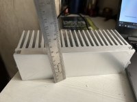
Further progress and work cutout for the weekend
It’s going to be 2 mono blocks on one heatsink sized 215mm x 70mm x 75mm rated at 0.5k/w
It’s going to be 2 mono blocks on one heatsink sized 215mm x 70mm x 75mm rated at 0.5k/w
Attachments
Last edited:
Mr Elvee,
The excellent performance of my previously built MOSFET Circlophone prompted me to build another Circlophone but this time on a proper Class A all aluminium chassis. The last one was built of a salvaged metal cabinet where in I could not fit large heat sinks for output devices. Even with inadequate heat sinks the amplifier is working very well till today.
This time I have checked all components like resistors, capacitors to their actual value and even matched input and VAS transistors on component tester. I have glued input pair transistor BC546B with heat sink compound and bonded them with Araldite. In this build I have used Cascode transistor KSA1381 instead on Zener diode.
I have used soft start circuit to prevent inrush current.
Although this chassis has a provision for Volume Control but I will not use it since putting volume control at the input increases distortion even with a low value of 5K pot.
The build has following parameters;
1. Rail Voltage - 32V
2. Offset Voltage - between 3-4 mV (Both Channels)
3. Quiescent Current - ~164ma (input short)
Components Used
1. Transistor BC546 - CDIL India
2. Transistor 2N5401 - KEC
3. Transistor VAS KSA1381 (ON Semi)
4. Transistor Cascode KSA1381 (ON Semi)
5. Transistor CCS - MPSA42
6. Power Schottky - MBR745 (Taiwan Semiconductor)
7. Signal Schottky - BAT85
8. Output MOSFET - IRFP240
9. Current Sensor Resistor - 1Ohm MOF
10. Other Resistors - MFR
11. Toroidal Transformer - 24-0-24 5 Amp
12. Rail Capacitors - 2 pair of 10000MFD 63V (Samwha)
Both channels are silent with no input.
Again thanks for your excellent schematic design.

I have heard his built recorded via a phone and it sounded very nice.Well done Katiyar: it is an absolute beauty. In comparison, my own builds are absolute crap (even though they sing beautifully)
Elvee you have given us a very lovely amplifier. ☺️
This would be my first discrete build.
Hoping my build also goes well.
Last edited:
This is remarkable in the wiring, in view of the short distance between the mains voltage and the output sockets.
But great that there are amplifiers that are built on SMD.
My boss would fire me.
Maybe learn the Ohm's law...
Think times the amplifier of Aditya for his nursery is.
just ask, if you have no idea.
But great that there are amplifiers that are built on SMD.
My boss would fire me.
Maybe learn the Ohm's law...
Think times the amplifier of Aditya for his nursery is.
just ask, if you have no idea.
Hey Oscar,Think times the amplifier of Aditya for his nursery is.
just ask, if you have no idea.
I do not get your comments could you please be more clear and in an understandable language.
What do you want to say regarding my board - be clear.
Dear Aditya, I think that was not correct in the translation. No your effort and the time and of course the money what you have invested for your project, is commendable for me.
Nevertheless, I and others would be interested in where you want to use the Circlophone ?
But a project that is now over 10 years here with us in the forum, to bring back to life, with probably some
problems or also errors I find good.
I will present the Circlophone in May 2023, at a conference in Munich Germany.
As it looks like your layout, you use Sprint layout ?
Firstly i have to thank you very much for your kind words and appreciating the effort, and yes the Translations were realy off making me confused as to what you wanted to say.Dear Aditya, I think that was not correct in the translation. No your effort and the time and of course the money what you have invested for your project, is commendable for me.
Currently i am planning a stereo for my room with a PGA2311 as an attenuator and Relays to select the inputs - TV, Raspberry Pi Streamer, its still in WIP.Nevertheless, I and others would be interested in where you want to use the Circlophone ?
If someone wanted the board (if it worked correctly then max to max as a GB with or without parts).
I really appriciate the help from everyone. I am also trying to get a NAD3020 in my style, just for nostalgia ( I am not that young also ).But a project that is now over 10 years here with us in the forum, to bring back to life, with probably some
problems or also errors I find good.
I wish you all the best, and also my heart is there with you for the presentation as it is something i would love to do and meet new people, but i have some other priorities.I will present the Circlophone in May 2023, at a conference in Munich Germany.
No i do not use Sprint, I am using something else so i get to have schematic and PCB integrated incase something is changed in schematic. Alot didAs it looks like your layout, you use Sprint layout ?

@oscargolf could you clear out what your translations ment for @katiyar amp we got really confused.
Last edited:
Dear Aditya, thank you for your reply !
Oh bringing a NAD 3020 back to life would be a great idea. Built in Japan and if I'm right between 1979-1982 ?
I come more, to my person, from the Philips area and served the company for years.
But dear Aditya, it would be nice if you would write us about a success, I assume.
Thanks a lot
Oscar
Oh bringing a NAD 3020 back to life would be a great idea. Built in Japan and if I'm right between 1979-1982 ?
I come more, to my person, from the Philips area and served the company for years.
But dear Aditya, it would be nice if you would write us about a success, I assume.
Thanks a lot
Oscar
Hello OscargolfAs an electronics technician and engineer, I would like to thank you once again for
for the wrong translation.
Please be considerate due to my advanced age (83 years). Thank you....
None Taken, you are most welcome. Just one think stay active here as much as -> it gives us the encouragement.
Regards
Aditya
Hi Guys,
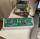
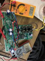
Ok so I have assembled both boards, and powered by +/- 21 DC,
The build has following parameters;
1. Rail Voltage - 21V
2. Offset Voltage -
Orange meter Left channel 3.2 to 3.6mV
Red Meter Right channel 0.9 to 1.3mV
3. Quiescent Current - ~150mA (input short)
4) Heatsink Temp after Half hour - ~ 40
degree centigrade.
5) I will be checking the outputs on scope once I can manage one. Currently my meter’s frequency counter does not show any oscillation. ( not the best way but still).
Components Used
1. Transistor BC556B - Philips
2. Transistor 2N5551 - On Semi
3. Transistor VAS - KSC3505 + 4.7pF (ON Semi)
4. Transistor CCS - MPSA42
6. Power Schottky - MBR745 (Taiwan Semiconductor)
7. Signal Schottky - BAT85
8. Output Transistor - 2SC5200N
9. Current Sensor Resistor - 1Ohm
10. Other Resistors - MFR
11. Toroidal Transformer - 16-0-16 4.5 Amp
12. Rail Capacitors - 3 pair of 4700MFD 63V (Samwha)
Problem - how to make left side offset similar to right side.
Attachments
Excellent technical parameters. Offset is extremely low very difficult to achieve. I could not achieve below 2mv in hot condition. Congratulations on your success.Ok so I have assembled both boards, and powered by +/- 21 DC,
- Home
- Amplifiers
- Solid State
- ♫♪ My little cheap Circlophone© ♫♪