Good one ☝️. Viva circlophone 🖖What you hear is not the air pressure variation in itself
but what has drawn your attention
in the streams of superimposed air pressure variations
at your eardrums.
Siegried Linkwitz RIP
Everything has long been invented before us. Here is a model of a similar amplifier published in 1980.
Many developers attach great importance to the quality of work at low power.
Compare the two options.
Many developers attach great importance to the quality of work at low power.
Compare the two options.
Attachments

This is not my design, I just gave food for thought. If someone is annoyed by such information, then do not read, pass by. There is a patent for a similar amplifier structure, but I can’t find it now. Sometimes, instead of inventing the bicycle, it makes sense to look at what has already been invented. I end with this. Thank you for your attention.Please open your own thread comparing amplifier simulations rather than polluting this one. Thank you.
Best regards
I made clear from the start that the Circlophone is not a super-amplifier, boasting sub-ppm distortion levels, etc. It is simply a modest, relatively simple but good amplifier, exceptionally easy to build, well-behaved and tolerant: it has been built with output devices having a Ft ranging from 0.07MHz to 100MHz, germanium transistors, darlingtons, NMOS, etc. No one has been mad enough to try horizontal deflection transistors, but it could probably be made to work. It can be built in any part of the world (and it has been), even in the most deprived parts of Africa and Asia, using randomly salvaged components
It has been adapted for low-voltage, single-supply, etc., all without issues.
It is an ugly little duckling, but it is incredibly graceful and and effective, which is why I decided to publish it instead of binning it.
Some unholy combinations of output and VAS transistors cause instabilities, but they can be fixed easily, and are mostly harmless: no one has ever reported a fried tweeter.
Regarding the originality, we all know that everything has already been invented twice at least, but if this is such a reinvention, it is a pleasant variant for many people.
Here are some more reinventions to sink your teeth into: https://www.diyaudio.com/community/...here-is-the-legacy-thread.387391/post-7051987
Instead of denigrating/sniping at a despicable design, why don't you show the world your exceptional talents, by proposing a simpler, cheaper, better and more effective design?
Open your own amplifier thread instead of wasting your time on a worthless design, and wow us all.
In the mean time, you can go on with your criticisms on this thread: it remains open to all opinions, including the most negatives
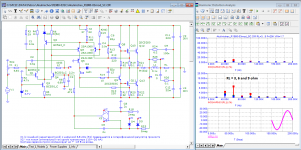
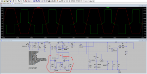
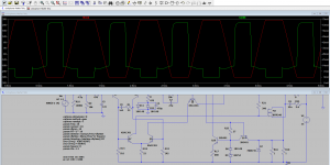
Mr Elvee, I need your expert openion on a possible modification to prevent VAS current overloading in case of an input over voltage at the input. In the MOSFET version I find that when the input signal rises to say 2V the VAS current in the cascode transistor rises to around 70ma from 13ma (slide1).
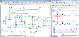
I have done a slight modification to the VAS circuit and added two transistors in the VAS circuit to bypass the excess current going to the base of VAS transistors in case of over voltage at the input (slide 2). I have found that with such an arrangement the current through cascode transistor reduces to around 30ma from 70ma at 2V input signal voltage. In such an arrangement the output signal is perfectly clipped as was previously without this arrangement. The THD does not change with this modification.
How would this modification effect the performance and can I implement this modification in my build.
I shall be thankful for your reply on this issue.
Attachments
Last edited:
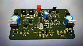
Hi OscarCongratulations for the, yes you can say full amplifier combo, looks very good ! Really very good (super) !
Also thanks for using the PCB layouts I provided.
Yes, the transistors 2N3019 are hard to get, I would have had to make a small change in my layout so that you could also use other transistors Q5,Q6 e.g. in the TO 126 housing. I use 2SC2690.
Thanks Oscar
You used 2sc2690 instead of 2n3019. In the semiconductor comparison table it says 2sd669 can be used instead of 2sc2690.
My question is, will we solder 4.7pf cap between 2sd669 base collector?
I am sure you can implement it: it is completely transparent during normal operation, and only kicks into action when overload occurrs.How would this modification effect the performance and can I implement this modification in my build.
IIRC, the problem has already been raised and examined, maybe by Kenpeter.
There must be an alternative solution somewhere in the thread, by yours is perfectly acceptable
The capacitance is 14pF, which is more than enough.Hi Oscar
You used 2sc2690 instead of 2n3019. In the semiconductor comparison table it says 2sd669 can be used instead of 2sc2690.y question is, will we solder 4.7pf cap between 2sd669 base collector?
The 2SC2690 has 26pF, which is marginally too high
ThanksI am sure you can implement it: it is completely transparent during normal operation, and only kicks into action when overload occurrs.
IIRC, the problem has already been raised and examined, maybe by Kenpeter.
There must be an alternative solution somewhere in the thread, by yours is perfectly acceptable
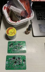
was working on a powersupply board with protection, finally i think its done. But DIY is never Done.
Edit - Right after i finished posting it, I realised I need to add LED for Speaker Protection.....
Should I add a 0.22 or 0.33 ohm resistor between the Power caps.

Edit - Right after i finished posting it, I realised I need to add LED for Speaker Protection.....
Should I add a 0.22 or 0.33 ohm resistor between the Power caps.
Last edited:
its a simple UPC1237 based circuit with T90 relay as well feature where in a user could use SSR instead of Relay.Looks a well designed board but for the benefit of the boarders what is the other circuit on the left side of the board. is it a speaker protection circuit and if so on what circuitry is it based?
once tested by me , This could be available as GB
It can help in reducing the current peaksShould I add a 0.22 or 0.33 ohm resistor between the Power caps.
@Elvee
I would like to know if I wanted to incorporate 2SC5200, while running the amp at no more than +/- 35 volts and a load of 8ohm driver.
Could i do it and what would i need to change.
the reason for this are
1) 2SD1047 is also 20MHz like 2SC500 so why not the later.
2) MJL(W)21194 are less than scanty on Reputed distributors or sellers.
Note: - I do have 5 MJL21194 and but what if i loose some..
3) 2N3055 are but no decent Heatsing and i want to stay away from using L plate for mounting to standard heatsink.
4) Availbilty of TIP3055 ( TO-247) but rated as the lowest in that ranking.
5) want to have some stock of replacement parts.
you guidance will be quite helpfull for me to proceed.
I have seen his board and it’s a very nice layout but I already got my BJT smd board 100 x 63 having option for zener and ccs as well as cascode. Even procured the parts so making a mosfet one will be a wait.In my opinion, Circlophone is a perfect MOSFET amplifier. I wouldn't go for BJT output devices with new builds if there's no some compelling reasons. Bangla H's PCB at post #1810 is a very good one
Attachments
- Home
- Amplifiers
- Solid State
- ♫♪ My little cheap Circlophone© ♫♪