Thanks...In principle, you just need to adjust the value of the G-S resistors.
The compensation components might need some optimization too.
Hi Rajesh, what is your experience with Tomson electronics other than CDIL made transistors? Do they sell original ST made transistors like Tip3055/Tip35C etc?Mr Aditya, My name is Rajesh and I am from Lucknow.
You can buy original BC546, BC556, 2N5551 & BD140 CDIL transistors online from a shop called "Tomson Electronics". This shop is based in Kerala. Web address Tomson Electronics | Wholesale Electronics Store in India
– TOMSON ELECTRONICS.
Best Regards
Mr Elvee, I want to increase the output power of MOSFET Circlophone to around 200W for my second build . The present setup is at 35V DC with IRF350 output MOSFET transistor. I donot have any more IRF350 so I have to change the transistor to probably IRFP240. Can I parallel three MOSFET with current limiting resistors and gate stopper resistors at 55V DC supply.
Thanks
Katiyar
Thanks
Katiyar
In principle, it could be done. All the external resistors should be kept to an absolute minimum: a good matching is essential, and should allow for very low or even zero source balancing resistors (see Peufeu's work on the subject), and as the gate resistors degrade the phase margin, they should also be minimized.
This is possible with a good layout, but multiple devices sometimes tend to turn into a push-pull oscillator and require some mitigation measures: provision a resistor on the PCB, but try to use 0 ohm first. If it doesn't work, try 10, 22, 47 ohm or even better a 500nH or 1µH ferrite bead, but keep it to the minimum required
This is possible with a good layout, but multiple devices sometimes tend to turn into a push-pull oscillator and require some mitigation measures: provision a resistor on the PCB, but try to use 0 ohm first. If it doesn't work, try 10, 22, 47 ohm or even better a 500nH or 1µH ferrite bead, but keep it to the minimum required
Thanks.
Also I propose to use 0.22 ohm current limiting resistor. Your view on this?
Also my next querry is whether to parallel three devices together or to use a high power single device.
Thanks
What could be the minimum value you suggest. The present build does not have any gate resistor.gate resistors degrade the phase margin, they should also be minimized.
Also I propose to use 0.22 ohm current limiting resistor. Your view on this?
Also my next querry is whether to parallel three devices together or to use a high power single device.
Thanks
Last edited:
If your current design works without stopper, try to keep it that way by mounting the pralleled devices physically close.
0.22ohm is OK. When the amp is built, measure the quiescent voltage drop across the resistors to make sure the sharing is balanced enough.
A single device would be preferable, but for 200W out, I do not see which easily available device could be used
0.22ohm is OK. When the amp is built, measure the quiescent voltage drop across the resistors to make sure the sharing is balanced enough.
A single device would be preferable, but for 200W out, I do not see which easily available device could be used
Hi all !
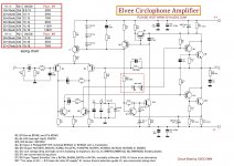
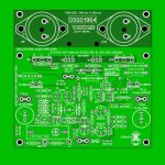
Thanks for your contribution!That is my PCB and Circuit-Draw from the Elvee Circlophone View attachment 1052359
I will reference it in the build thread
Hi all !
here are the Gerber files in RS274x format.
Please note that I have ordered the boards and will report soon if everything works. But I think it will work.
I think some names are missing for the end transistors.
How did it look with the 2N3773 , they should also work or?
I think there was already a post about it. But I can't find it anymore.
I need the buffer for a VU meter with the BA6822S IC.
The BA6822S only has an input resistance of approx. 300 ohm.
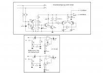
The switch-on delay with DC voltage protection was once a school project of mine. I'll get back to you when I can send you the first pictures of the working Circlophone. Something else on my own behalf, please!
I come from Germany and my English is not so good. Please excuse that. Thanks and many thanks to ELVEE. Greetings Kai.
Attachments
Please share Sprint File. ThanksHello, I can send you the sprint layout file.
@oscargolf thank you sharing your layout. At last we have a single layout for both metal and plastic power transistors which I tried before but never finished. I would like to see finished boards with retro looking metal transistors. I tested 2n3773's before and they're OK like any other metal NPN power transistors that I have tried before (mostly 1-4MHz range).
Hello everyone, first of all thank you very much for the nice answers and questions. So developing a circuit board that is stereo and has a protective circuit on board is actually not that difficult.
I'll give it some thought. I would like to write something about my protection circuit, the aim was to make it as simple as possible. I think the "Or" circuit for the light-emitting diodes is OK. However, the protective circuit is very sensitive to very low DC voltages. It already reacts at approx. 1V DC.
The relays are intended for approx. 70 watts at 4 ohms. I don't need more power. And the relays are very cheap. But I will take this into account in my project for a stereo version, so that other switching relays can also be used. The TO-3 transistors will then probably be drawn at a 45° angle. But it will take some time until I have drawn a reasonable version of a complete Circlophone. Thanks a lot for now.
Translated with www.DeepL.com/Translator (free version)
- Home
- Amplifiers
- Solid State
- ♫♪ My little cheap Circlophone© ♫♪


