Yes , I have read all the threads on Vbe's (bias generators). I did read all relevant info in both Self's 5th edition and Cordell's book. I am still frustrated.
I even tried Rod Elliot's more basic method of tempco.
My first try was spanning a 4 OP device amp across 2 heatsinks with the drivers and Vbe on the front heatsink (1 of the 2) , this was stupid .. I knew better. That resulted in a unbalanced OPS , 1 pair stabilized at 16mv and the other at 8mv. I did run it long enough (failure) to see that it slowly creeped up in temperature.
My second attempt was with this same "span" (stupid again) , but with a separate driver heatsink. In this case , the unbalance happened again , but the average dissipation was quite solid at 12mv (average/16mv front - 8mv back - unbalanced) this would be the case between freezer and hairdryer (-5C - 70C).
My 3rd attempt (arggggg) is the present one. It has the drivers/Vbe on the main heatsinks , each amp has it's own heatsink.The good thing is that both heatsinks/amps are the same temperature. Still , especially with the bias turned up (22mv-.22Re/100ma+) , it shows signs of thermal runaway. Bias creeps up to 30+mv within an hour and keeps on going.
I tried to increase the coefficient of the Vbe by using higher gain devices (Ksc3503-F/ 150hfe and ksc2690-Y / 300hfe !!). This improved the speed of the bias generator but the thermal "creep" was still there. I also tried Elliot's suggestion of reducing the current in the vbe resistor divider to 1/12th that of the transistor. This reduced the problem further , but I could not achieve "flatline" or negative tempco with any combo of currents or devices.
I realize I am trying to compensate the 2 device's Vbe's with a single device and the MJE15033/32 - njw0281/0302 pair might have too much positive coefficient for a simple Vbe to deal with. I am about to go "round 4" with this , if the japanese can do it ... so can I !! Any suggestions would be very helpful and would be tested out "real world" .
OS
I even tried Rod Elliot's more basic method of tempco.
My first try was spanning a 4 OP device amp across 2 heatsinks with the drivers and Vbe on the front heatsink (1 of the 2) , this was stupid .. I knew better. That resulted in a unbalanced OPS , 1 pair stabilized at 16mv and the other at 8mv. I did run it long enough (failure) to see that it slowly creeped up in temperature.
My second attempt was with this same "span" (stupid again) , but with a separate driver heatsink. In this case , the unbalance happened again , but the average dissipation was quite solid at 12mv (average/16mv front - 8mv back - unbalanced) this would be the case between freezer and hairdryer (-5C - 70C).
My 3rd attempt (arggggg) is the present one. It has the drivers/Vbe on the main heatsinks , each amp has it's own heatsink.The good thing is that both heatsinks/amps are the same temperature. Still , especially with the bias turned up (22mv-.22Re/100ma+) , it shows signs of thermal runaway. Bias creeps up to 30+mv within an hour and keeps on going.
I tried to increase the coefficient of the Vbe by using higher gain devices (Ksc3503-F/ 150hfe and ksc2690-Y / 300hfe !!). This improved the speed of the bias generator but the thermal "creep" was still there. I also tried Elliot's suggestion of reducing the current in the vbe resistor divider to 1/12th that of the transistor. This reduced the problem further , but I could not achieve "flatline" or negative tempco with any combo of currents or devices.
I realize I am trying to compensate the 2 device's Vbe's with a single device and the MJE15033/32 - njw0281/0302 pair might have too much positive coefficient for a simple Vbe to deal with. I am about to go "round 4" with this , if the japanese can do it ... so can I !! Any suggestions would be very helpful and would be tested out "real world"
.OS
![P-CAD EDA - [Sheet1].jpg](/community/data/attachments/202/202258-691ffa71f88a92fecbbb87231374539e.jpg)
![P-CAD EDA1 - [Sheet1]0001.jpg](/community/data/attachments/202/202280-3934535d5ea0a1bae7549abcee3afe5c.jpg)
Yes , I was considering designing a different Vbe. My question to those that know is whether I should just redesign for separate driver / outputs since I have to make a new board regardless (below 1). Self and Cordell both say compensating 2 junctions is much harder.
Are separate driver - output thermal arrangements better or worse ?? What is the effect of ambient temp. on the separate drivers ? I notice most projects go in this direction ... I really want to keep the simple 1 device Vbe. The layout does not give many options (ventilation + 1 heatsink away from it's circuitry).
OS
Attachments
To keep the things simple: just try to improve thermal coupling or your Vbe transistor. AKSA uses to screw it directly on top of one of the OP, if I remember well. It does not look lelegant maybe, but surely it is much more better coupled that way.
Otherwise, just screw the VBE transistor without any insulation on the H/S (I suppose a SOT126 or TO220 device). This should be possible if it is the only one doing so and the H/S is insulated from chassis.
Otherwise, just screw the VBE transistor without any insulation on the H/S (I suppose a SOT126 or TO220 device). This should be possible if it is the only one doing so and the H/S is insulated from chassis.
Ostripper, have you read Bob Cordells thoughts on Vbe spreaders and looked at any of his circuits in his book? I have something on my website also, but admit its a bit complicated and perhaps not entirely practical.
In my current amp I use a small SOT23 devies as a sensor in a CFP Vbe spreader and I go from 120mA to 140mA cold to very hot.
In my current amp I use a small SOT23 devies as a sensor in a CFP Vbe spreader and I go from 120mA to 140mA cold to very hot.
Separate drivers case has not even one advantage. You need extra space on PCB, separate heatsinks, not having control over temperature of drivers etc. If only BIAS current vs. temperature compensation is an issue than design correct Vbe compensation and that's it.
I absolutely agree , my triple op for sub will have a more exotic Vbe. This one is short on space and hard to layout. With separate drivers , the drivers are not thermally coupled , you only have the feedback of the OP's to Vbe. If the drivers were cold , gain is reduced ,Op's are cool ... vbe responds to just the OP's.
By tekko - Strange. My diy amplifiers never had this problem, they rather almost compensate a bit too much, dropping the bias.
Describe "my DIY amps" ..... I am interested (HS / Vbe / devices)
By effebi - just try to improve thermal coupling or your Vbe transistor. AKSA uses to screw it directly on top of one of the OP
Yes , Vbe on a short ribbon cable - I have a spare threaded hole right next to one of the OP's (less than 1cm).
OS
Ostripper, have you read Bob Cordells thoughts on Vbe spreaders and looked at any of his circuits in his book? I have something on my website also, but admit its a bit complicated and perhaps not entirely practical.
In my current amp I use a small SOT23 devies as a sensor in a CFP Vbe spreader and I go from 120mA to 140mA cold to very hot.
I saw your Vbe (smd) , very nice
.. I read chapter 14 of cordell's book.OS
All the texts I have read suggest the drivers in EF types I,II & III have very little current variation, from nil to max signal. There is little benefit putting them any place in particular so just adequate, separate sinking is typical. The quiescent variation is far greater in the output devices and that's what we all know is the place to sense EF stage temp.
Both Self and Cordell offer several approaches to varying tempcos, sufficient to cover about anything, so maybe there is a problem with overloading the Vbe multiplier, which is easy, due to small loop gain in the case of with a single device. I don't know what you have at the moment but perhaps a look at whether it is generating according to plan is possible?
I guess that implies a temp. v bias plot which may not be simple. Another longshot is to separate the driver sinks and see if they are being affected by the O/P stage.
Last edited:
All the texts I have read suggest the drivers in EF types I,II & III have very little current variation, from nil to max signal. There is little benefit putting them any place in particular so just adequate, separate sinking is typical. The quiescent variation is far greater in the output devices and that's what we all know is the place to sense EF stage temp.
Both Self and Cordell offer several approaches to varying tempcos, sufficient to cover about anything, so maybe there is a problem with overloading the Vbe multiplier, which is easy, due to small loop gain in the case of with a single device. I don't know what you have at the moment but perhaps a look at whether it is generating according to plan is possible?
I guess that implies a temp. v bias plot which may not be simple. Another longshot is to separate the driver sinks and see if they are being affected by the O/P stage.
I am just about at that point in the "real world" (below 1). As you see , I have 2 channels , separated by the red zones on the same PCB. Where you see "Vbe" there is a screw hole 1cm from a output device.With the back amp "R bias" I am forced to run a long (7-8cm) flat cable to the Vbe (no room at the back for circuitry) , the front should be a short run... "L bias". I have more room at the "bias's" , to even make a different Vbe , as I made my multipliers smaller and more compact . The drivers are now separate as they were in attempt #2. That attempt actually had a slightly negative coefficient but unbalanced operation spanning 2 heatsinks.
Also , in the case of the separate drivers , I noticed very little variation between Idle or heavy use.I tried the Elliot way of manipulating tempco : Elliott Sound Products - Audio Power Amplifier Design Guidelines
"design of bias servo". By using combinations of (C-B to B-E 2.2k/700 , 2.7K/1K and 3.3K/1.2K) , I was able to change the rate of tempco even as it still fell short of negative coefficient with the driver /OP's on the main HS. Ksc2690 and sc3503 are way better than the MJE340 for Vbe devices , making the reaction faster by at least 3 times.
I don't know what you have at the moment
(Below 2) Just a standard EF2 on just barely big enough OEM heatsinks (120w X 2 nikko amp). so you have both my layout and circuit. Works and sounds fantastic except for this issue.
OS
Attachments
Last edited:
Ksc2690 and sc3503 are way better than the MJE340 for Vbe devices , making the reaction faster by at least 3 times.
OS
VBE bias transistors are to be carefully selected to have
low Vbe and high gain.
As such, the MJE340 is irrelevant while the two others
are better due to higher gain, no doubt.
As a clue, here a Trans. devellopped for this application,
you can always find one that is cheaper and available
by comparing to this one..
http://www.sanken-ele.co.jp/en/prod/semicon/pdf/2sc4495e.pdf
These work for me:
C-B = 1K
B-E = 200R
VR = 1K (preferably multi-turn)
No creep. Drivers on power heatsink with OP.
You use mostly "metal cans" , I think lower Hfe than my to-3P's = not as much required tempco. The NJW21193/4 pair is easily overcompensated by the same bias generator that can barely compensate my EF. Infact , your Vbe R ratio is close to what I use on the 21193/4 = 1.2K/ 220/ 500R (VR). These values would also be slightly different by Vbe device or heatsink C/W.
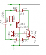
By PMA-This circuit helps to get almost zero tempco of idle current:
(one may need to tune resistor values to fit the amplifier used)
I saw this in my "wanderings" , is that the "feared" CFP Vbias ?? Some say instability could occur. What happens if the wiper on R6 opens ??
I might use one of these on my triple (cordell's "diamond" triple - pre and driver cancel tempco ) but would want "zero day" indestructability. Wahab , that is a cool device. The IC/vbe and Hfe delta plots are way different than your normal fairchild /ON , plastic package , even marketed as a "thermal compensation device". MCM has them - $1.40USD (my other account besides mouser)
OS
This "CFP" bias has higher dV/dT compared to standard circuit. I have designed it during PA2/PA4 development. With conventional circuit, I measured quite different idle current for cold and heated amplifier. With this circuit, the difference between cold start idle current and heated amplifier idle current is negligible. Drivers and the BD135 are on the same heatsink with output devices.
Regarding reliability, no problem during 1 year operation. The trimpot is high quality multiturn Vishay-Spectrol. All bias circuit parts run at little power, no worries needed.
Regarding reliability, no problem during 1 year operation. The trimpot is high quality multiturn Vishay-Spectrol. All bias circuit parts run at little power, no worries needed.
Last edited:
Why drivers not on main heatsink? You want them hot?
Why Vbe not in the middle od heatsink?
You like to complicate a little.
"drivers not on main heatsink" ?? they would be far hotter on the main heatsink (heated by the outputs). I tested this exhaustingly , biased to 12ma (150Re) , the drivers on a separate heatsinks only increased 10C while the OPS increased by 30+C.
With the driver/ops on the same heatsink, both drivers and OPS increased 30+C.
I don't often listen to my "first watt" .... I go all the way (hot).
Vbe should NOT be in the middle of the HS , thermal "delay" would occur. The heatsink near the Vbe would be 5+ C cooler than it would 1cm from a output device (or mounted on top of it), resulting in "lag" between OPS heating and compensation.
I do not "complicate" , the Nikko heatsinks can go from room temp. to 50C and back to room temp in 120 seconds , very fast to dissipate.. with twice the surface area of a normal DIY heatsink (70 large fins per heatsink - VERY efficient). This would be advantageous to keep Xover distortion lower but harder to compensate for than the big fat block of DIY aluminum .
OS
- Status
- This old topic is closed. If you want to reopen this topic, contact a moderator using the "Report Post" button.
- Home
- Amplifiers
- Solid State
- Vbe problems ... I'm going nuts !!