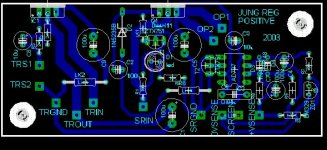
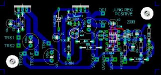
This is my first desing of a PCB for the Jung SuperReg. The desing is from ALW site, see http://www.alw.audio.dsl.pipex.com/jung_schematic.htm.
Using this schematic and some others on the web, and also all the discussion that I red on this forum, I came up with this first version of the PCB. There is a complete ground plane on the top of the PCB. A small schematic showing the parts number and the connexion names will follow.
Any Comments will be welcome.
Attachments
Hi,
Thanks for the link to the ALW site. I hadn't read it before. And congrats to Andy W on a great site!
I looked at your schematic from the zip file, and if I understand the description of the regulator/pre-regulator connection from the ALW site correctly, the pre-reg is actually supposed to stack on top of the output of the super-reg. In other words, what's shown as GND of the LM317 portion of the circuit should really be floating on top of OP1/OP2. The pre-reg is set for 2.5 Volts output (gain of 2 to a 1.23 Volt bandgap reference), so I think the idea is to have it produce 2.5 Volts VCE for Q1.
From Andy W's site:
"The Kelvin sense point TRS1 or TRS2 is connected to the regulator output (OP1 or OP2), the pre-regulator output is then connected to the Super Regulator input (TROUT to SRIN). The raw +ve supply is then fed in on TRIN, the tracking regulator input."
Pre-Reg purpose
Further in ALW very good article, he mentionned that the pre-reg output is then set: "2.5V above the super-reg output". This is why the Pre-Reg resistors are set for 2.5V.
Here the other schematic that I used. It is showing very clearly the pre-reg connexion. It used it also to configure the gnd star points. The differents gnd points are very well explained.
Attachments
Why the post
I just produce an Eagle version of the PCB so others DIY can use it if they like. This is also a compilation, at just one place, of the numerous pages I had to read/search throught to get everything right. Just to get the negative version of the Jung reg (Not on ALW site by the way ) took me more time than necessary
  . I didn't mean any disrespect for ALW works. Since I don't know ALW real implentation of his PCB and parts choice, and that I used only freely available info on the web to produce this compilation, I tried not to hurt any body feeling.
DIY is also building thing by ourself, for our own use") . Even if the ALW regulators are available (and I didn't know they were since I couldn't find any order/prices info on ALW's site
. Even if the ALW regulators are available (and I didn't know they were since I couldn't find any order/prices info on ALW's site  ), I would had build my own. It is also probably cheaper for me since I will use a lot of parts that I have in stock to build it...
Just by the comment of Andy_C, that didn't know about ALW site, I will probably help ALW get more sell and more traffic on his web site.
I just produce an Eagle version of the PCB so others DIY can use it if they like. This is also a compilation, at just one place, of the numerous pages I had to read/search throught to get everything right. Just to get the negative version of the Jung reg (Not on ALW site by the way
) took me more time than necessary . I didn't mean any disrespect for ALW works. Since I don't know ALW real implentation of his PCB and parts choice, and that I used only freely available info on the web to produce this compilation, I tried not to hurt any body feeling.DIY is also building thing by ourself, for our own use
. Even if the ALW regulators are available (and I didn't know they were since I couldn't find any order/prices info on ALW's site ), I would had build my own. It is also probably cheaper for me since I will use a lot of parts that I have in stock to build it...Just by the comment of Andy_C, that didn't know about ALW site, I will probably help ALW get more sell and more traffic on his web site.
That explains the explosion of webhits!
Boy my weblog's been going mad, now I know why!
Looks a lot like my Jung PCB
I'm flattered that anyone should choose to copy my PCB design, it's the sincerest form of praise, but there is an easier way
I do sell these, but don't promote it, simply because I couldn't cope with big demands. I only sell the kits upon request for that reason - I did the board for my own use, but the demand was overwhelming. I've sold over 100 so far, through word of mouth.
It's not been unknown for me to send the Gerber or Eagle files to non-UK residents, solely because it's often less hassle than me supplying kits with my current workload.
I do have a negative version available too, as is mentioned in the manual I have available on my website.
I'd also add that some things may have changed since a lot of my website was written, if you read my postings here you'll be able to deduce some of them, actual customers get free upgrades
The pre-reg adj pin does connect to the super-reg o/p and produces an input voltage 2.5V above the o/p, i.e. it maintains 2.5V across the super-reg. This scheme has advantages and disadvantages, but the overall balance is this scheme works best, but if I were doing it again now, I would do things differently.
The basic PCB works well though, both sonically and technically and is a good basis for comparison with mod's to the design or alternative topologies. They're stable and trouble-free.
The board posted above does have one advantage though - the 3x7 adj pin cap is now on-board.
It has a BIG disadvantage though - the AD797!
The AD825 is more stable and sounds better - and the board above has no SOIC option. The schematic on my site shows the AD797, 'cos I was too lazy to do and AD825 symbol in Eagle.
Don't use the AD797
Enjoy!
Andy.
Since you are at it why not line up all the in/out pads and distance/size them for some screw type connectors
I get the feeling that a regulator with potentially an o/p Z in the uOhm range (depending upon error amp) would be better with soldered connections.
Screw terminals?
We're not into mass-production here are we
Andy.
I see what you mean
Andrew was kind enough to send me a copy of his manual that I was able to open. Sorry Grataky, you where right, most of the info that I provided on this post is there.
Andrew, you are right. My PCB is almost identical to yours and I used only your parts location and schematic to guide me. I guest that in this case the form follow the function
I will use the AD825 then.
Thanks Andrew to be such a great help.

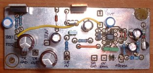
Positive Reg completed
I just finish my prototype of the Positive reg. Working just fine without any oscillation. I'm using the AD825. Found a small error on my PCB with C6. Did a small correction on the PCB. I will post the final Pos/Neg version when I'm done.
I will try to build the negative version this week.
To try their sound I will use them to supply my SuperDAC op-amp line stage and see if they improve the sound compare to a simple LM317 supply.
- Status
- This old topic is closed. If you want to reopen this topic, contact a moderator using the "Report Post" button.
- Home
- Amplifiers
- Solid State
- My Jung SuperReg PCB