Hi,
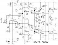
I found this amp on the net and I'm interested in building one. Can you guys please comment on this?
http://web.tiscali.it/audiofanatic3...iSS/350W_BD750A_BD751A/350W_BD750A_BD751A.jpg
Thanks,
JojoD
I found this amp on the net and I'm interested in building one. Can you guys please comment on this?
http://web.tiscali.it/audiofanatic3...iSS/350W_BD750A_BD751A/350W_BD750A_BD751A.jpg
Thanks,
JojoD
I’d use OPA604 instead of TL071. I made this change in my old Quad 405-2. The difference between the chips is big enough to try this mod. But if you use the zener supply with the OPA604 you will experience problems when switching the amp on and off.
I recommend you to find in the net and read an article on Quad 405 mods, written by Bernd Ludvig. He suggests replacing the zeners with transistors. It works fine.
Regards
I recommend you to find in the net and read an article on Quad 405 mods, written by Bernd Ludvig. He suggests replacing the zeners with transistors. It works fine.
Regards
 .
. and heed my own tag line until I've read the entire schematic...
Hi again!
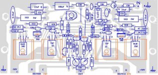
What is C16 and C17 for? It seems to be placed across the wrong pins of the tip31/32???
In the schematic it is placed across the collector and emitter. However in the pcb it is placed across the base and collector
Which one is correct? The schematic or the pcb design?
JojoD
What is C16 and C17 for? It seems to be placed across the wrong pins of the tip31/32???
In the schematic it is placed across the collector and emitter. However in the pcb it is placed across the base and collector
Which one is correct? The schematic or the pcb design?
JojoD
Attachments

Looks like a pretty typical design.
I will say that if you get 300W from only 2 devices per rail, you'll be pretty lucky. I guess you might with a higher voltage 75-90V rails but you had better have a hefty heat sink and fan to cool those poor transistors.
Good luck,
Chris
I will say that if you get 300W from only 2 devices per rail, you'll be pretty lucky. I guess you might with a higher voltage 75-90V rails but you had better have a hefty heat sink and fan to cool those poor transistors.
Good luck,
Chris

"It seems this amp has a lot of errors. "
yep. The longer I lokk, the odder it looks. For instance it looks like nfb is applied to both the inverting and non-inverting inputs. Add to that the compensation caos (at least I think that's what they are intended be) in ops being possibly in the wrong spot, the rails bearingr little relation to the power implied to the name (unless tha's "music power" x 2 channels), and I would definately make SPICE simulation of it (just to see if it remotely works) before I spent a penny on components.
My interesst lies in the idea of using an opamp as an input stage. The notion is it would make the unit simpler to construct and reduce the pcb "real estate" So far it seems the components that need to be added to get it to work with the discrete stages nearly cancel out the advantages I had imagined.
If I read it right, C6 is the filter for the zener on the negative rail..... Yes, it is backwards! The posative goes to ground and negative to the negative rail.
My mistake, I was sleeping. I see the 4 outputs now..... Yup! It should do. Still, a large H.S. is in order and maybe a fan!!!!!
Chris
My mistake, I was sleeping. I see the 4 outputs now..... Yup! It should do. Still, a large H.S. is in order and maybe a fan!!!!!
Chris
I have only one schematic, but it contains no opamp:
310W/4ohms
There is another one, with opamp, but lower output power:
275W/4ohms
Sajti
310W/4ohms
There is another one, with opamp, but lower output power:
275W/4ohms
Sajti
- Status
- This old topic is closed. If you want to reopen this topic, contact a moderator using the "Report Post" button.
- Home
- Amplifiers
- Solid State
- Anyone built this amp?