Attachments
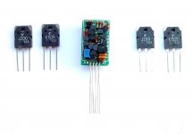
Neat little daughter board, but it eludes me why they use TO-92 in such PCB placement density instead of SMDs. Just about every one of those transistors, equivalent or better, come in SMD packages. I see more commonly SOT-323 now. I just incorporated the 'discreteness' of the op-amp-like circuit into the main PCB. This photo export from Eagle is 5.7cm X 3cm, a small part of the new amp I'm creating, the IPS. Q3, Q4, Q8 are SOT-923, 0.8cm X 0.6cm. Although this circuit isn't like a traditional op-amp circuit, it does have more parts.
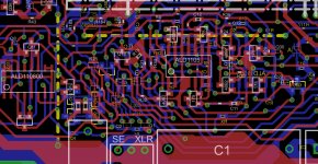
This photo export from Eagle is 5.7cm X 3cm, a small part of the new amp I'm creating, the IPS. Q3, Q4, Q8 are SOT-923, 0.8cm X 0.6cm. Although this circuit isn't like a traditional op-amp circuit, it does have more parts.Attachments
but it eludes me why they use TO-92 in such PCB placement density instead of SMDs.
That's my next hurdle , I'm sure some of the " big" SMD BJT's can handle 6-7ma with the collector soldered to a large copper pad. I want to get voltage stages down to a couple sq. inches. Must be nice , just etch ... and solder (with magnifying glass
) .OS
I've found myself fond of 2SC6026/2SA2154 from Toshiba. Very handy indeed to use as current gain amplifiers in cascode amp, I measure Ai for these at ~300, Ic=1mA. If Vce is 4V, 5mA is not a problem. The pad layout would be difficult to do home etching for though.:dodgy Super SOT-6 Pd is usually >1/2W.
IMHO, lower VAS bias means you need more current gain for the OPS, but it allows you to use small signal devices. There are certain advantages to using small signal transistors for voltage gain.
IMHO, lower VAS bias means you need more current gain for the OPS, but it allows you to use small signal devices. There are certain advantages to using small signal transistors for voltage gain.
Last edited:
- Status
- This old topic is closed. If you want to reopen this topic, contact a moderator using the "Report Post" button.
- Home
- Amplifiers
- Solid State
- Power Op_Amp