Influence of power amplifier output coil and speaker cable to frequency response
We like to measure our amplifiers into purely resistive, non-inductive load. Is it easy? Yes, it is. Is it right? I do not think so. I am developing a novel method to measure power amplifiers and as a byproduct I have found very obvious thing – the speaker cable and amplifier output coil both influence frequency response at speaker box terminals in a way, that is not negligible at all.
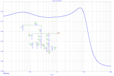
Let's first see a real world situation with speaker cable but no output coil. The amplifier is assumed as an ideal voltage source with zero output impedance for now. We add cable and terminals resistance (R99 = 0.02 ohm), cable inductance (L3 = 3uH) and cable capacitance (C49 = 50pF). Changing L3 to 2uH or so does not affect results much. The rest of the circuit are equivalent circuits of woofer and tweeter and C4 is the simplest high pass cross over possible.
Now let's measure behind the speaker cable, at speaker box terminals. The voltage measured is V(out1). Let's make a frequency response plot and see what is happening.
We like to measure our amplifiers into purely resistive, non-inductive load. Is it easy? Yes, it is. Is it right? I do not think so. I am developing a novel method to measure power amplifiers and as a byproduct I have found very obvious thing – the speaker cable and amplifier output coil both influence frequency response at speaker box terminals in a way, that is not negligible at all.
Let's first see a real world situation with speaker cable but no output coil. The amplifier is assumed as an ideal voltage source with zero output impedance for now. We add cable and terminals resistance (R99 = 0.02 ohm), cable inductance (L3 = 3uH) and cable capacitance (C49 = 50pF). Changing L3 to 2uH or so does not affect results much. The rest of the circuit are equivalent circuits of woofer and tweeter and C4 is the simplest high pass cross over possible.
Now let's measure behind the speaker cable, at speaker box terminals. The voltage measured is V(out1). Let's make a frequency response plot and see what is happening.
Attachments
From the previous post we have seen that the influence of speaker cable to frequency response at speaker box terminals is not negligible in the real world speakers. It is quite different from frequency response into resistive load.
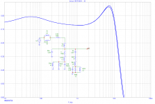
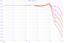
Now let's add a usual part of most power amplifiers, the output coil. The output coil L6 = 2uH (quite usual value) and it has damping resistor R100 in parallel. We shall step this resistor from 1 ohm to 10 ohm, again quite usual values.
In the image attached we can see the result. The output coil of 2uH affects frequency response above 10kHz substantially. The damping resistor R100 does not help much to change this situation.
Attachments
Hi Pavel!
Very interesting results, thanks to share it with us! Somehow I was aware about that but never simulated to see the results.
That's way I prefer to put the mono-bloc amps right at the back of the speakers and use long interconnect, high quality, cables.
By the way ... I never used output coil in any of my amps.
Cheers,
Mihai
Last edited:
the cart is difficult to read. Are we talking about 0.02dB difference?The output coil of 2uH affects frequency response above 10kHz substantially.
Regards
the cart is difficult to read. Are we talking about 0.02dB difference?
Regards
No. This 0.02dB is the difference between 1 ohm and 10 ohm damping resistor in parallel with output coil.
The difference between "output coil" and "no output coil" is about 0.2dB at 20kHz (in this particular case), it is the difference between images in Post no.1 and Post no.2
Last edited:
Hi Pavel!
Very interesting results, thanks to share it with us! Somehow I was aware about that but never simulated to see the results.
That's way I prefer to put the mono-bloc amps right at the back of the speakers and use long interconnect, high quality, cables.
By the way ... I never used output coil in any of my amps.
Cheers,
Mihai
Hi Mihai,
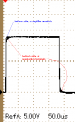
thanks for your comment. I was always aware of the fact that there would be "some difference", but never analyzed and quantified before. Few days ago I made a measurement comparing square impulse response before and behind speaker cable, with real loudspeaker box as a load. From time response it was obvious that there was an influence even in audioband, not only ultrasound band difference. So I started to simulate and simulations did confirm the measurements. I am attaching the time domain measurement, but the amplifier used has no output coil, so it is the influence of speaker cable (2m approx.) + speaker complex impedance.
Regards,
Attachments
Last edited:
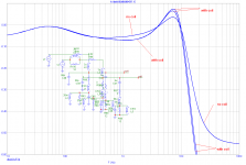
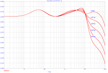
We can see the differences of frequency responses "with output coil" and "without output coil" if we put both plots into one image, as shown now.
Anyway, we can also see the influnce of speaker cable impedance to frequency responses - this would depend on cable used and overall speaker impedance vs. frequency response.
Anyway, we can also see the influnce of speaker cable impedance to frequency responses - this would depend on cable used and overall speaker impedance vs. frequency response.
Attachments
We can see the differences of frequency responses "with output coil" and "without output coil" if we put both plots into one image, as shown now.
Anyway, we can also see the influnce of speaker cable impedance to frequency responses - this would depend on cable used and overall speaker impedance vs. frequency response.
Wow! That's a whopping +/-0.02dB deviation in freq response! That can surely be cleary heard; I'll gladly sacrifice some stability and reliability for that big improvemment in sound quality Pavel!

jan didden
Jan, the tolerance band affected by cable and coil impedances is not 0.02dB, but about 0.3dB - 0.7dB in audioband, with resonant peaking. This is similar to small change in a speaker crossover tuning, and IMO more audible than -80dB of THD. I guess that you will also gloss in threads where guys are fighting with -100dB vs. -120dB harmonic distortion. What is more audible, what would you think?
Wow! That's a whopping +/-0.02dB deviation in freq response! That can surely be cleary heard; I'll gladly sacrifice some stability and reliability for that big improvemment in sound quality Pavel!
jan didden
Jan, for better demonstration of the output coil influence, let's assume extremely short speaker cable, that means that cable inductance is omitted. Now we can see just the contribution of output coil, for 0.02 ohm amplifier output impedance.
Attachments
Jan, for better demonstration of the output coil influence, let's assume extremely short speaker cable, that means that cable inductance is omitted. Now we can see just the contribution of output coil, for 0.02 ohm amplifier output impedance.
Right. 0.3dB @ 20kHz. For those that can still hear 20kHz, of course, which is probably all our kindergarten members.
And not counting the fact that the amp Zout also goes up at above 10kHz.
jan didden
And not counting the fact that the amp Zout also goes up at above 10kHz.
jan didden
Yes, just for the reason of output coil used.
How realistic is 0.02R for o/p+cable resistance? Low resistance can amplify the effect of reactance. At higher frequencies the amp output impedance will not only rise, but probably become reactive too - inductive? Let's pluck some figures out of the air. Say 0.01R for cable, 0.01R for the amp at DC. Assume the amp open-loop rolloff starts at 100Hz - should be OK as an order of magnitude for an SS amp? Then the amp output impedance is actually 0.01R with 16uH in series, before you add your coil. If you don't like these figures then pluck some different ones.
How realistic is 0.02R for o/p+cable resistance? Low resistance can amplify the effect of reactance. At higher frequencies the amp output impedance will not only rise, but probably become reactive too - inductive?
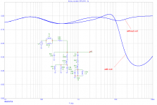
Here is the simulation for the real life amplifier, the one with which I do measure the influences mentioned. The simulation is for no series resistance added, and output coil stepped from 0 to 4uH. The amp itself has no output coil, it is designed not to use it.
Attachments
OK, that suggests that in simulation your amp has much less than 0.02R resistance and much less inductance. How that translates to the real world I don't know.
Have you plotted the input impedance of your crossover+drives? It seems to be going suddenly very low above 10kHz, and maybe very capacitive too?
Have you plotted the input impedance of your crossover+drives? It seems to be going suddenly very low above 10kHz, and maybe very capacitive too?
- Status
- This old topic is closed. If you want to reopen this topic, contact a moderator using the "Report Post" button.
- Home
- Amplifiers
- Solid State
- Influence of power amplifier output coil to frequency response