A cap parallel over Q8s and Q9s gate?
R10 needs to be on the order of 10 uF not 1 pF as was in one of the earlier schematics.
Can't adjust quiescent current... I think my software causes it.
No it doesn't. You should be able to adjust the current in the simulator in the exact same way as you do in real life -- by varying R11. Reduce it in the sim until you get a reasonable Q-current.
~Tom
ilimzn;2563091 . This means the crossover distortion will have it's own even order distortion because the crossover region is not symetrical -> 4th harmonic and above will be created. 240 and 9140 are much better complements. [/QUOTE said:What crossover distortion ? that was got rid of by the correct bias.
As I said bias and feedback sort out a lot of problems.
What crossover distortion ? that was got rid of by the correct bias.
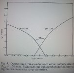
The crossover and specific harmonic distortion ilimzn pointed out is created by the significant difference in Gm vs Id between the two supposed complementary devices. The reason for extra bias with mosfets is they have reduced Gm with lower Id, <150mA, producing a region in the operating load line where transconductance significantly drops. 150mA bias will 'bridge the gap' between the two components around the output current zero crossing so the sum of the Gm from both components remains more constant. (see photo...ref B. Cordell) Distortion is created when the Gm slope of one device differs from the other, particularly around the zero current crossing. Using source ballast resistors of different values can also help mitigate differences in Gm between the 'complementary' pair, reducing distortion. Since there are high freq components correlated with crossover distortion, some of this distortion will elude the PM of your FB loop and present a representation of itself at the output. Some say these high frequency components are not audible, I disagree. Also if the FB loop is presented with even an AF distortion, because of the limited BW of the feedback loop, this distortion is translated to higher orders of frequency beyond the loop BW. The results from this is what gives feedback a bad reputation. The solution is to present the FB loop with as linear of a 'problem' to solve as possible. This means understanding where distortion components originate and how they permeate themselves inside your circuit 'system', and most importantly how to reduce them. Dwelling on these issues is how original designs become improved.
 It is the primary motivation behind DIY audiophile-mania.
Attachments
Can't adjust quiescent current... I think my software causes it.
Click with mouse on the schematic.
After this you can adjust with potentiometer.
2.5 A is not normal for a class AB design. I'd expect Q-currents on the order of 100 mA. Unless you're talking the supply current at full output. That's hardly relevant for DC bias.
In the sim, replace the pot with a fixed resistor and change its resistance until you get a reasonable DC bias point.
~Tom
In the sim, replace the pot with a fixed resistor and change its resistance until you get a reasonable DC bias point.
~Tom
If you look at the graph in post 25, the ideal situation would be to have Gm a horizontal line wrt Id. As much as there must be adequate bias to bridge the gap in Gm vs Id, too much bias can create Gm doubling, since the output is the sum of the two. This is less of a problem with mosfets because of thier lesser transconductance than BJTs but 2.5A with verticals might be too high. 2.5A would be more suited to class A, but then in that case there is no crossover gap in Gm to overcome.
2.5A would be more suited to class A, but then in that case there is no crossover gap in Gm to overcome.2.5 amps ? I use 7ma on my irfp240/9240 amplifiers and there is no visible crossover distortion on the scope.
I was talking about the current when there is an 8 ohm load. Sorry if I wasn't clear.
About the thermal compensation:
How can I calculate R1 and R2? One of the two resistor could be a pot to adjust quiescent current, right?
About the thermal compensation:
An externally hosted image should be here but it was not working when we last tested it.
How can I calculate R1 and R2? One of the two resistor could be a pot to adjust quiescent current, right?
What we know is that MOSFET has about 4 Volt Gate to Source VGS
So if you attach for R2 one 3.9k resistor we get 1mA.
This is a good value.
As there are two MOSFET at output we need 4V+4V to bias.
We make R1 the same 3.9k
Now is like 8 Volt across the IRF610
If you make R1=R2=3.9k, we should be close to some current in output.
If it is too much, then lower R1
If it is too little current then increase R1
You can use 2 resistors to get a good value for R1
It seems that I can adjust the quiescent current right now
I used the following schematic
An externally hosted image should be here but it was not working when we last tested it.
I used the following schematic
An externally hosted image should be here but it was not working when we last tested it.
Not bad after all?
Also simulated the THD
Any remarks?
What about the quiescent current, I've used 344mA in my simulations, is there a significant difference (sound) between the 150mA that CBS240 advised?
Also simulated the THD
An externally hosted image should be here but it was not working when we last tested it.
An externally hosted image should be here but it was not working when we last tested it.
Any remarks?
What about the quiescent current, I've used 344mA in my simulations, is there a significant difference (sound) between the 150mA that CBS240 advised?
Last edited:
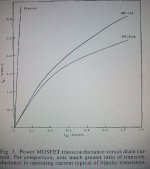
Starting to look a bit better, results are better. As for the 344mA bias, refer to post 29 and the Gm doubling issue. This can create crossover like distortion that is just as difficult for the FB loop to deal with. (mistake in post 29, I meant to say ideally Gm vs Id is a vertical line, but then nothing is ideal in the real world.) You can see the comparison of
Gm vs Id(c) between BJTs to Mosfets and get an idea why the bias of BJTs is in the 10-50mA range and Mosfets require more, 100-150mA range. These points are important in determaining the optimum bias current of a class AB output stage.
There is more detail on this subject in this paper.
) You can see the comparison of Gm vs Id(c) between BJTs to Mosfets and get an idea why the bias of BJTs is in the 10-50mA range and Mosfets require more, 100-150mA range. These points are important in determaining the optimum bias current of a class AB output stage.
There is more detail on this subject in this paper.
Attachments
Last edited:
 Thanks lineup , from 66mV to 15mV DC-offset.
The amp is indeed getting decent.
Last thing will be the DC-protection. My first amp 9240/240 had a bad ground connection, I was lucky that I tested the offset everytime I wanted to play some music with is. It had -16V at the output! I've found something with a diac&triac from G. Randy Slone his "High Power Audio Amplifier Construction Manual" are there other possible ways to protect your speakers from lethal DC?
The Diac and Triac sounds like a crowbar and is effective but can be destructive. It was introduced by Quad in the 405 power amp. Once triggered it is "non resetable" untill the current through it reduces to zero. It can also cause further damage to an amp once triggered. The amp fuses must be suitably rated so as to actually blow in the event it triggers.
All normal DC protection schemes have the drawback of taking a finite time to operate, pehaps 20 milliseconds or so due to the time constant of the integrator network and the time it take a relay to drop out. Also most relays are not up to the job of disconnecting an inductive load from a large DC current... it will draw an arc welding the contacts together.
Its one aspect of design that few seem to test...
It's a crowbar indeed, but it isn't really a problem that it's unresetable until the current is zero. Or is it? I don't want flying cones and burning tweeters in my room.
Edit: What about a bunch of power resistors to 'eat' the DC-voltage or another contact to break the rail voltage?
Edit: What about a bunch of power resistors to 'eat' the DC-voltage or another contact to break the rail voltage?
Last edited:
Burning tweeters won't happen... the crossover will protect from that.Its burning woofers that is a real possibility. As an engineer (in sillier moments) we used to connect old speakers across rather large voltages sometimes (as you do for fun) and believe me, voice coils do catch fire.
The best normal DC protection can do is minimise damage and provide a safety factor.
IMO, a reliable switch on delay coupled with an ultra rapid switch off, so that the amp powers up and down silently is essential.
A DC protection is harder to make than I tought...
What are the reasons that DC can go to the speakers?
One of them is that the output devices fail. But I've read that BJT's 'close', and MOSFET's 'open' when they fail.
I don't know whether IRF**** do the same thing, the writer was talking about L-Fets
What are the reasons that DC can go to the speakers?
One of them is that the output devices fail. But I've read that BJT's 'close', and MOSFET's 'open' when they fail.
I don't know whether IRF**** do the same thing, the writer was talking about L-Fets
Any fault really can cause a DC offset. Yes bjts almost always fail short circuit. IRF type devices also fail short. Laterals are unique... they behave differently and are amazingly tough against abuse.
Ultimately a well designed and built amp thats not abused should not suffer failure... or is that a bit optimistic!
If an amp suffers from say oscillation or starts running hot and there is a few moments as the output climbs to one rail or another then offset protection has a chance to work.
Ultimately a well designed and built amp thats not abused should not suffer failure... or is that a bit optimistic!
If an amp suffers from say oscillation or starts running hot and there is a few moments as the output climbs to one rail or another then offset protection has a chance to work.
- Status
- This old topic is closed. If you want to reopen this topic, contact a moderator using the "Report Post" button.
- Home
- Amplifiers
- Solid State
- Easy and low cost: IRF540/9540 amp