Some time ago I noticed comments on D.Self book from Samuel Groner.
The part I would like to show now was about Triple output stage.
http://www.sg-acoustics.ch/analogue_audio/power_amplifiers/pdf/audio_power_amp_design_comments.pdf
It was this part of explanation that intrigued me to simulate an amp with this triple, but with bootstrapped CCS.
Depending on saturation characteristics of I2 and I3 this configuration
will yeld higher output swing compared to other triplr output stages.
For best efficiency these current sources could be replaced with bootstrapped
resistor loads, although this might result in somewhat reduced bias stability
with unregulated power supplies.
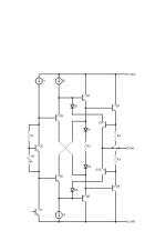
here is Groner triple as in his text.
The part I would like to show now was about Triple output stage.
http://www.sg-acoustics.ch/analogue_audio/power_amplifiers/pdf/audio_power_amp_design_comments.pdf
It was this part of explanation that intrigued me to simulate an amp with this triple, but with bootstrapped CCS.
Depending on saturation characteristics of I2 and I3 this configuration
will yeld higher output swing compared to other triplr output stages.
For best efficiency these current sources could be replaced with bootstrapped
resistor loads, although this might result in somewhat reduced bias stability
with unregulated power supplies.
here is Groner triple as in his text.
Attachments
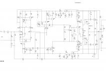
Amp with Groner Triple
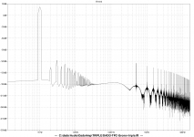
Simulation result.
distortion 1kHz 0.000012%
distortion 10kHz 0.000086%
distortion 20kHz 0.000318%
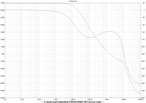
I attached circuit diagram, FFT, OLG, CLG, square wave on 8ohm and 8ohm//2uF
I had to add C19 an C22. Without them square wave diagram had ringing and overshoots.
It did not influence Opel Loop Gain.
J3 and J4 are constant current sources.
dado
Simulation result.
distortion 1kHz 0.000012%
distortion 10kHz 0.000086%
distortion 20kHz 0.000318%
I attached circuit diagram, FFT, OLG, CLG, square wave on 8ohm and 8ohm//2uF
I had to add C19 an C22. Without them square wave diagram had ringing and overshoots.
It did not influence Opel Loop Gain.
J3 and J4 are constant current sources.
dado
Attachments
-
 DADO-TMC-Groner-triple-sch.png110.7 KB · Views: 1,023
 -
 DADO-TPC-Groner-triple-FFT.png144.5 KB · Views: 977
 -
 DADO-TMC-Groner-triple-OLG.png153.9 KB · Views: 861
 -
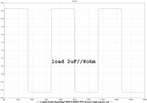 DADO-TMC-Groner-triple-square-2uF.png46.4 KB · Views: 234
 -
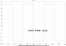 DADO-TMC-Groner-triple-square-0.png45.8 KB · Views: 227
 -
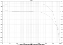 DADO-TMC-Groner-triple-CLG.png152.5 KB · Views: 862
How does this compare to for example one triple darlington output stage?Simulation result.
distortion 1kHz 0.000012%
distortion 10kHz 0.000086%
distortion 20kHz 0.000318%
This is an output design I'd like to investigate.
How does this compare to for example one triple darlington output stage?
This is an output design I'd like to investigate.
lineup,
It is very similar with triple EF. If you like to read more about this Groner triple follow the link I put in the first post.
What I did is just bootstrapp and FET CCS.
To know real difference soundwise it will be necessary to bild this amp.
dado
Looks like a double diamond buffer to me. A good circuit concept thats been around for quite a while. I like the bootstrap J-fet CCSs. J-fets make the best CCS don't you think?")
In simulation I used 2N3819, but in real bild I would use Supertex DN3135 or DN2535 high voltage vertical deplation mode DMOS fets excellent for CCS. I could not find spice model(for LTspice) for this FET.
http://www.datasheetcatalog.org/datasheet/supertex/DN3135NW.pdf
dado
Groner Triple or
Phoenix Triple?
http://www.diyaudio.com/forums/solid-state/174218-rebirth-phoenix.html#post2313409
Phoenix Triple?
http://www.diyaudio.com/forums/solid-state/174218-rebirth-phoenix.html#post2313409
Yes , I am hours (or days) away from some sort of triple. Myself, B. Cordell, and many others discussed a similar type of circuit : http://www.diyaudio.com/forums/solid-state/149324-self-type-3-ef-hybrid-triple-any-pointers.html
I never got around to actually build it , but this now changes. I need a good sub amp . I have the PCB almost designed (below) and the cascoded luxman or blameless modules to hook to the triple. After seeing this groner/phoenix configuration , I feed "bold" with my couple square inches of PCB "real estate".
To have the required "overkill" , I will use ksa/c 1381/3503 , njw0281/0302 , njw21193-4 (pre/driver/main OP)
OS
Myself, B. Cordell, and many others discussed a similar type of circuit : http://www.diyaudio.com/forums/solid-state/149324-self-type-3-ef-hybrid-triple-any-pointers.htmlI never got around to actually build it , but this now changes. I need a good sub amp
. I have the PCB almost designed (below) and the cascoded luxman or blameless modules to hook to the triple. After seeing this groner/phoenix configuration , I feed "bold" with my couple square inches of PCB "real estate".To have the required "overkill"
, I will use ksa/c 1381/3503 , njw0281/0302 , njw21193-4 (pre/driver/main OP)OS
Attachments
choices ??
I am considering all possibilities for this triple instead of just using the "standard" Leach circuit. This "sub amp" will also be shared as my "PB150" with audiophile full range use as the design goal. I don't want a restricted bandwidth power stage to detract from the performance of the better modules. The only thing I most likely won't do is use the Jfet CCS , I'm a BJT "purest" (cheeep)
OS

choices?? simple
Wow ! Those Russians are doing almost exactly what I propose ,
An externally hosted image should be here but it was not working when we last tested it.
.: SibAudio :. - Óñèëèòåëè -> Âûñîêîêà÷åñòâåííûé óñèëèòåëü ìîùíîñòè "SIBAUDIO-B2"
thanks for link.
Supertex has spice models for download:
Supertex - SPICE Models
I tried it but LTspice does not recognize it.
If predriver and drivers are mounted on the same heathsink its temperature coefficient will canceled and what is left to compensate are output transistor,
This is a big issue that I have seen dealt with in various ways. Predrivers will not dissipate much more than their class A bias irregardless of load. Drivers and output device junctions will vary wildly in their dissipations depending on source and load (subwoofers especially). To put the whole deal (russian amp above) on the same heatsink , the 3 sets of junctions would directly negate 3 - mur120 (or 3 t-track diodes). A triple OPS does not just require a Vbe that compensates for just 1 junction. If you put the driver/output or just the output on the main HS , you still need a "3 Vbe". Observe the leach amp (only OP's on main HS). Vbe response will be quicker this way , but some negative coefficient must be added to the Vbe to compensate for the ambient room temperature . Some OEM's use a PTC resistor in parallel with the normal C-B resistor of the Vbe or an extra diode junction there for just this purpose.
(below 1 - APT ) is the one type of triple Vbe, using just the single device. (below 2 -luxman) is the luxman with it's 3 diodes. Both the luxman and APT have pre and driver on separate Heatsinks. The luxman's 3 diodes set the negative coefficient for the 3 junctions of the OPS and the non- coupled transistor sest the coefficient for the ambient (room temperature). The luxman will keep 60mA bias from 0C to 40C ambient easily ... superior
. OS
Attachments
another invention of the wheel
ETMC triple?
http://www.diyaudio.com/forums/soli...erview-negative-feedback-301.html#post2352970
Cheers,
E.
ETMC triple?
http://www.diyaudio.com/forums/soli...erview-negative-feedback-301.html#post2352970
Cheers,
E.
bias stability
Not necessarily, see: http://www.diyaudio.com/forums/solid-state/174218-rebirth-phoenix-8.html#post2396749
Cheers,
E.
............
Depending on saturation characteristics of I2 and I3 this configuration will yeld higher output swing compared to other triplr output stages.
For best efficiency these current sources could be replaced with bootstrapped resistor loads, although this might result in somewhat reduced bias stability with unregulated power supplies.
...............
Not necessarily, see: http://www.diyaudio.com/forums/solid-state/174218-rebirth-phoenix-8.html#post2396749
Cheers,
E.
Welcome back Edmond.
Re-Re invention of the wheel
Pioneer used this topology in more refined version in two or three of their exclusive no global feedback amps back in the 80s.
- Status
- This old topic is closed. If you want to reopen this topic, contact a moderator using the "Report Post" button.
- Home
- Amplifiers
- Solid State
- Groner Triple