Not necessarily, see: http://www.diyaudio.com/forums/solid-state/174218-rebirth-phoenix-8.html#post2396749
Cheers,
E.
although this might result in somewhat reduced bias stability with unregulated power supplies.
...............
That is what I tried to solve with CSS boostrap in proposed schematic. Did you look at it?
dado
wheels
Thanks.
But for how long? I'm still involved with other things (my bike electronics and increasing the income of my GF, Iron Condors? )
)
Oh well........
Cheers,
E.
Welcome back Edmond.
Thanks.
But for how long? I'm still involved with other things (my bike electronics and increasing the income of my GF, Iron Condors?
)Re-Re invention of the wheel
Pioneer used this topology in more refined version in two or three of their exclusive no global feedback amps back in the 80s.
Oh well........
Cheers,
E.
although this might result in somewhat reduced bias stability with unregulated power supplies.
...............
That is what I tried to solve with CSS boostrap in proposed schematic. Did you look at it?
dado
Hi Dado,
I like to look at it, but where?
edit : gimme a link
Cheers,
E.
Last edited:
I believe Dado is referring to the ckt in post 2. I have used bootstrapping like this to supply the drivers in a HEC follower. This way I only need to regulate a few mA for the pre-driver stages. Works great! I plan to use a more refined version in my next proto.
Yes that it is, thanks CBS240.
dado
Wow, a circuit named after me ! As others have pointed out, there's is no reason for this, as it has been around for quite some time--just not with the attention it deserves, so I put it in my little paper.
Regarding replacing the CCSs with a bootstrapping arrangement: we need to carefully look at what actually limits output swing. If the small-signal stages of the amplifier are powered from a filtered/regulated supply which has lower voltage than the supply for the power transistors, the voltage swing limit will usually stem from the second stage, not the output buffer. In this case there is little reason to not just use CCSs.
Samuel
! As others have pointed out, there's is no reason for this, as it has been around for quite some time--just not with the attention it deserves, so I put it in my little paper.Regarding replacing the CCSs with a bootstrapping arrangement: we need to carefully look at what actually limits output swing. If the small-signal stages of the amplifier are powered from a filtered/regulated supply which has lower voltage than the supply for the power transistors, the voltage swing limit will usually stem from the second stage, not the output buffer. In this case there is little reason to not just use CCSs.
Samuel
bias stability
Hi Dado,
Of course you can do it that way and it should work.
But despite a perfect CCS, the OPS bias level still depends on the voltage of the main (and unregulated) power supply. To what extent depends on the Early voltage of the output devices. That's why I followed a different route to stabilize the bias level of the phoenix amp.
Cheers,
E.
although this might result in somewhat reduced bias stability with unregulated power supplies.
...............
That is what I tried to solve with CSS boostrap in proposed schematic. Did you look at it?
dado
Hi Dado,
Of course you can do it that way and it should work.
But despite a perfect CCS, the OPS bias level still depends on the voltage of the main (and unregulated) power supply.
To what extent depends on the Early voltage of the output devices. That's why I followed a different route to stabilize the bias level of the phoenix amp.Cheers,
E.
You really dislike a bootstrapping arrangement, don't you?
No--at places where it's use is appropriate. In the specific schematic suggested at the beginning of this thread it looks to me (without detailed study) as if the use of the bootstrapping would mostly increase complexity, and gain little.
Because of the electrolytics and/or old school practice?
Electrolytics are the first thing to fail in a well-designed circuit, so any less is an advantage, basically.
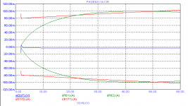
By the way, below the bias as function of the supply voltage.
Red: CCS
Green: Compensated bootstrap
Which of the two do you prefer?
Looks like an unfair comparison to me. Show us the bias stability of the bootstrapping version without any corrective arrangement. Such could be introduced for the CCS version as well.
BTW, do you know how dependable VA is in production (not a rhetoric question, I have no data on this)?
Samuel
Wow, a circuit named after me
Regarding replacing the CCSs with a bootstrapping arrangement: we need to carefully look at what actually limits output swing. If the small-signal stages of the amplifier are powered from a filtered/regulated supply which has lower voltage than the supply for the power transistors, the voltage swing limit will usually stem from the second stage, not the output buffer. In this case there is little reason to not just use CCSs.
Samuel
I called it that way to get some attention on that schematic. If there is not well known participant beyond the tread no one pays attention.
dado
No--at places where it's use is appropriate. In the specific schematic suggested at the beginning of this thread it looks to me (without detailed study) as if the use of the bootstrapping would mostly increase complexity, and gain little.
Compared to a CCS, a bootstrap isn't that complex: 2R's and 1 C.
Electrolytics are the first thing to fail in a well-designed circuit, so any less is an advantage, basically.
True, but in every amp you will need some electrolitics anyhow. So two more of them has little effect on the overall reliability.
Looks like an unfair comparison to me. Show us the bias stability of the bootstrapping version without any corrective arrangement. Such could be introduced for the CCS version as well.
I showed the compensated bootstrap as an answer on Dado's remark:
"although this might result in somewhat reduced bias stability with unregulated power supplies."
Of course you also can apply some form of compensation on a CCS.
BTW, do you know how dependable VA is in production (not a rhetoric question, I have no data on this)?
Samuel
I don't have exact data. I guess VA will vary as much as beta will. For a given process, VA * beta seems to be constant.
Anyhow, no matter which method is used (a CCS or a bootstrap), in both cases the Early effect will affect the bias stability (that is, with an unregulated PSU).
Cheers,
E.
I showed the compensated bootstrap as an answer on Dado's remark:
"although this might result in somewhat reduced bias stability with unregulated power supplies."
E.
That remark was taken from Groner text on that Triple.
So I changed one resistor with CCS(one MOFET and one resistor). In this case a bootstrap is 2 R's 1 C and 1 FET.
dado
Have you simulated with 4 and 2 ohm loads - if you plan to go that low?
I am not sure what you want to simulate.
Distortion on 2ohm is still very low.
1kHz 0.000045%
20kHz 0.001604%
Attached is LTspice zip file with sinus and square simulation, and you can try to test what is of your interest and show the result and comments.
dado
Attachments
Hi dado,
Maybe it's of no concern, but did you have a look at the effect of temperature of the CCS FETs on the OPS bias?
Cheers,
E.
Problem with my simulation is use of standard NJFET from LTspice library. I tried to use Supertex model(DN3135 or DN2540) but LTspice does not recognize it.
With a wrong model I don't see usefulness of temperature simulation. Do you know how to find Supetex spice models that LTspice can use?
dado
Problem with my simulation is use of standard NJFET from LTspice library. I tried to use Supertex model(DN3135 or DN2540) but LTspice does not recognize it.
As for the DN3135, the maximum temp. coef. of Vgs is 4.5mV/K.
So it's quite easy to simulate temperature effects. Just insert a (small) voltage source in front of the gate.
With a wrong model I don't see usefulness of temperature simulation. Do you know how to find Supetex spice models that LTspice can use?
dado
Sorry, I don't know (I'm using another simulator)
Cheers,
E.
- Status
- This old topic is closed. If you want to reopen this topic, contact a moderator using the "Report Post" button.
- Home
- Amplifiers
- Solid State
- Groner Triple