This will happens in other forum...not here...in this forum, boards
may be the original...the ones we start offering...the old style..without "L" adaptor...if i understood well...this is what Byron will do.
About the other forum, despite it is not you should worry, we are dealing with this modification.
Majority of guys are Brazilians...not only from Brasil but my friends..people that has assembled one or two amplifiers from the "corporation"
They use "L" shape adaptors and they have protection boards (delayed insertion, off set protection and thermal protection) and they will connect the thermal sensor to switch off when reaching high temperature...and this may not happens because they will use their amplifiers at their home.
I will provide schematic to the ones want to make the protector...i have all plans and also they have boards...i have also boards here and they can copy to produce by themselves.
They will be stimulated to buy heatsinks that already has a flange to reduce thermal troubles... some thermal grease will be suggested and this may help a lot... avoiding the adaptor, using the special heatsinks Hugh Dean from Aksa uses, then no problems about heat transference.
They will know..all them...about the thermal issues....i have made several videos about it and all them will be published there.
Do not worry...uncle charlie will be dealing with this problem.... visit this link and watch loudspeaker protection....i will provide this schematic modified to use 64 volts supplies:
regards,
Carlos
Attachments
Last edited:
Carlos,
i believe he is talking about the ilustration posted , it shows the outputs attached to the board before going to the angle. I'm sure this was an oversight and not what is actually going to be done.
that's exactly what i'm referring to a.wayne
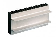
Well... i am confused.... boards offered may be these ones
Well... i have so many files here that i have to study.
So, no "L" shape adaptor to the diyaudio forum group buy...no flange, no special heatsinks.
Is that what you're talking about...i am Brazilian...my english is poor... write long text and explain what you mean with details or i will not be able to understand.
regards,
Carlos
Attachments
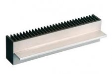
I continue confused....i am showing the boards we gonna use
in this forum... the idea that is better to heat transference..the most safe idea.
Not what i like..these images are not my prefered..but this is what i suggest....this is what is needed...this is the best solution.
I am not understanding the meaning of your message Woody...explain using more words....i am not a native english speaking guy....uncle charlie is brazilian.
regards,
Carlos
Attachments
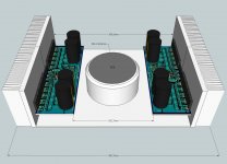
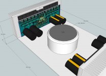
i'm referring to this picture
which clearly shows alexmm's large board mounted with the outputs mounted to the board then the board mounted to the angle so that the board is between the outputs and the angle so no heat transference between the outputs and the heatsink .
cheers Woody
An externally hosted image should be here but it was not working when we last tested it.
which clearly shows alexmm's large board mounted with the outputs mounted to the board then the board mounted to the angle so that the board is between the outputs and the angle so no heat transference between the outputs and the heatsink .
cheers Woody
Ahahahahahah!....yes!...now i got it
Transistor is touching the board in the place (instead) to touch the heatsink....yes...this was wrong..of course a mistake.
Well guys.... no one will do that...was a mistake while creating the 3D..of course no one will install transistors into the fiberglass.... i do think no one is retarded this way.
regards,
Carlos
Those images are better Carlos , the second one is bad only due to height of outputs..
As previously stated , the image you had originally picked did not show outputs to heat sink , instead to board, i had thought an oversight and not really the actually setup, woody now understands such ...
As previously stated , the image you had originally picked did not show outputs to heat sink , instead to board, i had thought an oversight and not really the actually setup, woody now understands such ...
Say i have to install transistors into the counselor, councilor, adviser, mentor
heheheh.... google is a hell confused.
regards,
Carlos
Haaa, ha lol... Portuguese name/ancestory .... not one word spoken ..
I have concerns about the L shape material
This is no good to high power amplifiers....better to install transistors directly into heatsink.
See video please:
Supercharged L adaptor heat transference issues - YouTube
Carlos
This is no good to high power amplifiers....better to install transistors directly into heatsink.
See video please:
Supercharged L adaptor heat transference issues - YouTube
Carlos
This is no good to high power amplifiers....better to install transistors directly into heatsink.
Carlos
thank you i totally agree !!!!
Woody
- Status
- This old topic is closed. If you want to reopen this topic, contact a moderator using the "Report Post" button.
- Home
- Amplifiers
- Solid State
- Dx Blame MKIII Supercharged will soon be released