I am needing another pcb layout designer, despite i have Alex mm
that is already very good...but busy... very busy!
I am having two more foruns to feed with boards, and i want now a different kind of layout as these two foruns (SMPS and diyaudio) are using the same layout....i want a different style...your style man!
Also i want another option, a Mini Hx, or "The son of Hx" to offer.... the same amplifier having only two output transistor, a single pair..and without room for "L" shape bracket to have it small and cheap.
Please, present your layout here, or contact uncle charlie using email adress:
nanabrother@hotmail.com
It is a non profit movement.... the same i use to do all these years..no one will receive any kind of payment or advantage..no boards as gift, anything..just our gratitude, the forum respect, the forum appreciation on you and your inclusion in the hall of fame from the Dx Corporation, second stage, main headquarters..with your picture surrounded by golden frame.
I have a demand...i want your board tested...if accepted, then must be tested prior to me to order and distribute...you must produce it, sample, and build, or must send me to me to build and test it... then we will start group buy using your gerbers (must provide them).
Also provide me all files from your software that can be different than Eagle...files you have used to produce your layout and to export files as Gerbers.
I want your authorization to use it for free, in wide world foruns.... without profit to anyone of us....no advantage to me, nor for you and not for the group buy manager... a free service for the audiophile community.
- "Join the Corporation where you have the good ones to be one of us!"
We are reaching 100 boards ordered...so...it is a sucessfull enterprise and i want you to join us.
http://www.youtube.com/watch?v=ujzSR6iL3Hk
regards,
Carlos
Last edited:
About pcboards.... i am nedding one more (at least) designer
About circuit boards - YouTube
regards,
Carlos
About circuit boards - YouTube
regards,
Carlos
This helped me to compare amplifiers while using the same supply...the same range of power.
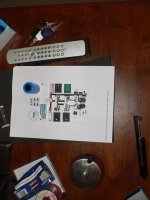
And i am showing you the schematic... basically the same amplifier... some parts replaced for tuning purposes and some parts are different because availability of these parts in my junk box.
It is not an amplifier released...it is just a curiosity for you.... i had fun producing smaller boards and using only two pairs in the output... it is sounding great..the same sound i have to the MKIII-Hx..... a little bit more high end because the smaller capacitor in the VAS....hehehe.... this made a lot of difference... VAS is the most important stage.... the most important tuning is made there.
The MKIII-Hx is already faster and have much more dinamics compared to the Supercharged MKII and the Dx Blame ST.... so....i found was unfair to compare them... would be a slaughter (heheheh)... then i decide to make them same power...same supply...this would result a more fair comparison.... sadly my camera is not able to register high frequencies..and there's the main difference between them:
Hx and St, a comparison - YouTube
regards,
Carlos
Attachments
I will decide what design to use in November
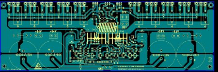
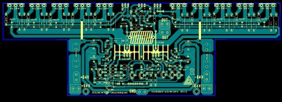
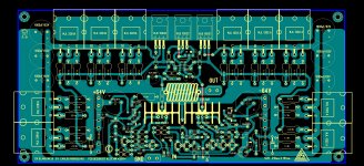
I do think i may use two or three different layout...i do like yours...send me gerber files in order to me to check layers... also i want more layouts....only silk screen in pdf, copper tracks in pdf and both combined, as a ray x view..silk screen and parts located upper the board and copper tracks that we can see if the board was transparent and made by glass..... will be needed also image in pdf, informing board dimension, in black and white...one with copper tracks in black to hot iron image transference made at home...and another with copper tracks in Black, in order to people use the photographic method to make image transference to a copper board covered by photo sensitive chemical material.
In advance to check, i will ask you please, dear Tayag, to check this with a lot of care...then i will check once again...it is normal, common for us humans, to make mistakes.
I do like your board layout.... i do appreciate how it looks....but i need more data... dimensions and details.... i have to inspect pads and copper thickness and distance in between copper tracks...distance from input to output and if some part may couple magnetically.
As i told folks in the video... i want this board produced as soon it receive approval, so, you may be able to do it, to assemble it by yourself for testing purposes and i will instruct you what kind of testing to perform... also that board can be shipped to my home and i can do that by myself if you want...not needed me to do... you can do that.
Inductances and capacitances present in a pcboard are too much complex to go imagining or calculating..we have to assemble to be sure the unit will not oscilate.... the only way we have to be sure is building..there's no other way.
We have two international diy foruns selling boards by cost price... i will let them exaust.... will be waiting them to finish, to manufacture boards, to ship to diy for free customer, will be waiting them to assemble, will give them follow up..and then i will think about to start in other foruns other group buys, using boards provided by diyaudio members....of course we can open group buy here for these new board layout designs...but only after the group buys that are running finish their job....many monthes to come.
Thank you very much Joel Tayag (drowranger)
Do not post gerbers here... pirates may use to produce boards and sell them in Ebay... they already have old gerbers from old amplifiers and they are still having fun..let them busy with old amplifiers... and this new one will be explored in our foruns.
I am posting your picture because you look good.... Dx Corporation members usually looks good..exception is the chairman..ahahahahaha")
regards,
Carlos
I do think i may use two or three different layout...i do like yours...send me gerber files in order to me to check layers... also i want more layouts....only silk screen in pdf, copper tracks in pdf and both combined, as a ray x view..silk screen and parts located upper the board and copper tracks that we can see if the board was transparent and made by glass..... will be needed also image in pdf, informing board dimension, in black and white...one with copper tracks in black to hot iron image transference made at home...and another with copper tracks in Black, in order to people use the photographic method to make image transference to a copper board covered by photo sensitive chemical material.
In advance to check, i will ask you please, dear Tayag, to check this with a lot of care...then i will check once again...it is normal, common for us humans, to make mistakes.
I do like your board layout.... i do appreciate how it looks....but i need more data... dimensions and details.... i have to inspect pads and copper thickness and distance in between copper tracks...distance from input to output and if some part may couple magnetically.
As i told folks in the video... i want this board produced as soon it receive approval, so, you may be able to do it, to assemble it by yourself for testing purposes and i will instruct you what kind of testing to perform... also that board can be shipped to my home and i can do that by myself if you want...not needed me to do... you can do that.
Inductances and capacitances present in a pcboard are too much complex to go imagining or calculating..we have to assemble to be sure the unit will not oscilate.... the only way we have to be sure is building..there's no other way.
We have two international diy foruns selling boards by cost price... i will let them exaust.... will be waiting them to finish, to manufacture boards, to ship to diy for free customer, will be waiting them to assemble, will give them follow up..and then i will think about to start in other foruns other group buys, using boards provided by diyaudio members....of course we can open group buy here for these new board layout designs...but only after the group buys that are running finish their job....many monthes to come.
Thank you very much Joel Tayag (drowranger)
Do not post gerbers here... pirates may use to produce boards and sell them in Ebay... they already have old gerbers from old amplifiers and they are still having fun..let them busy with old amplifiers... and this new one will be explored in our foruns.
I am posting your picture because you look good.... Dx Corporation members usually looks good..exception is the chairman..ahahahahaha
regards,
Carlos
Attachments

Last edited:
check this one
I do think i may use two or three different layout...i do like yours...send me gerber files in order to me to check layers... also i want more layouts....only silk screen in pdf, copper tracks in pdf and both combined, as a ray x view..silk screen and parts located upper the board and copper tracks that we can see if the board was transparent and made by glass..... will be needed also image in pdf, informing board dimension, in black and white...one with copper tracks in black to hot iron image transference made at home...and another with copper tracks in Black, in order to people use the photographic method to make image transference to a copper board covered by photo sensitive chemical material.
In advance to check, i will ask you please, dear Tayag, to check this with a lot of care...then i will check once again...it is normal, common for us humans, to make mistakes.
I do like your board layout.... i do appreciate how it looks....but i need more data... dimensions and details.... i have to inspect pads and copper thickness and distance in between copper tracks...distance from input to output and if some part may couple magnetically.
As i told folks in the video... i want this board produced as soon it receive approval, so, you may be able to do it, to assemble it by yourself for testing purposes and i will instruct you what kind of testing to perform... also that board can be shipped to my home and i can do that by myself if you want...not needed me to do... you can do that.
Inductances and capacitances present in a pcboard are too much complex to go imagining or calculating..we have to assemble to be sure the unit will not oscilate.... the only way we have to be sure is building..there's no other way.
We have two international diy foruns selling boards by cost price... i will let them exaust.... will be waiting them to finish, to manufacture boards, to ship to diy for free customer, will be waiting them to assemble, will give them follow up..and then i will think about to start in other foruns other group buys, using boards provided by diyaudio members....of course we can open group buy here for these new board layout designs...but only after the group buys that are running finish their job....many monthes to come.
Thank you very much Joel Tayag (drowranger)
Do not post gerbers here... pirates may use to produce boards and sell them in Ebay... they already have old gerbers from old amplifiers and they are still having fun..let them busy with old amplifiers... and this new one will be explored in our foruns.
I am posting your picture because you look good.... Dx Corporation members usually looks good..exception is the chairman..ahahahahaha
regards,
Carlos
Attachments
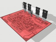
Interconnect your ground tracks in order to avoid us
To run wires....search for Alexandru's ground style and copy the style please.
There's a lot of run to develop your boards.....better vertical and horizontal alignment can be made....a more organized arrangements to components....alike soldiers in a parade, they go aligned vertical and horizontal.
I know you are still learning the stuff....a very good starting job you have done...then go ahea.
regards,
Carlos
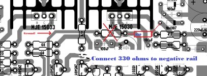
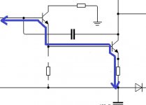
It has a mistake dear Alexandru...that 330 ohms resistance should
connect to the negative rail instead to be connected to ground...i have sent you a video explaining this...want me to post the video?
Please my dear...fix that as soon as you can as Meanman is waiting these files to order manufacturer to produce boards.
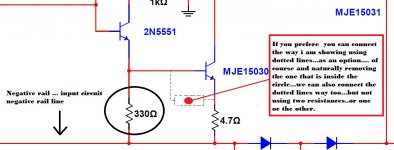
I am very sorry my first video had audio narrative saying to put it to ground...was my mistake...i do mistakes too...this is not your privilege...everybody does mistakes... then i made a yellow text superimposed to the video saying i was wrong.... saying the 330 resistance should go to the negative rail line...after diodes...the input circuitry negative rail line.
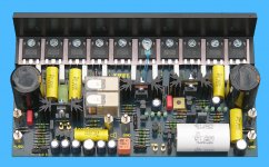
Image attached.... yes...if you need you can connect to the 4.7ohms resistance too, as it goes to negative and we can use it too (in an emergency, to make things faster and easy to you)
Can be alike meanman did...the colour image attached.
regards,
Carlos
connect to the negative rail instead to be connected to ground...i have sent you a video explaining this...want me to post the video?
Please my dear...fix that as soon as you can as Meanman is waiting these files to order manufacturer to produce boards.
I am very sorry my first video had audio narrative saying to put it to ground...was my mistake...i do mistakes too...this is not your privilege...everybody does mistakes... then i made a yellow text superimposed to the video saying i was wrong.... saying the 330 resistance should go to the negative rail line...after diodes...the input circuitry negative rail line.
Image attached.... yes...if you need you can connect to the 4.7ohms resistance too, as it goes to negative and we can use it too (in an emergency, to make things faster and easy to you)
Can be alike meanman did...the colour image attached.
regards,
Carlos
Attachments
Last edited:
.... no problem at all I can manage
Regards Alex.
Alex,
Can you also make a board with the following dimensions 265mm x 115 mm instead of 265mm x 87 mm?This way I could use an L bracket like in the pic
Attachments
Yes dear Meanman..... board was made that way to reduce size and this way we would
be able to reduce price...but if you can have the same good price having bigger board...then go ahead..it is fine to me...i do like this way.. was not applied as a sacrifice in order not to increase price.
About that resistance, well folks, if you want you can forget that resistance..we can say folks not to install them in the board too...not the best solution to say that but we can do that in an emergency when Byron had already fixed all stuff and made agreements with his board manufacturer.... circuit can operate without the resistance to negative, because it is there because i desire to adjust both VAS transistors VBE according to my own needs..some "matching" of VBEs or if you want to understand different, some "unmatching" of VBEs i wanted to have there.
Bias, polarization will be there anyway...with or without the resistor... watch the diagram and you will see the circuit can flow this way too... simulations and also my prototype worked great without problems when i have removed that resistance from the circuit.
Of course i would prefere to have it..but if Alexandru , or Byron or Meanman, because their own reasons, decide to keep the circuit the way it is and inform builders to remove that resistance..then it is OK to me too...i want to make your life easier..and also to provide a very good circuit to the community.
Alexandru finding some time to do it (he is busy), also Byron and Meanman, then you should fix the stuff installing the resistor in the correct place.
regards,
Carlos
Attachments
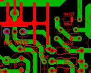
Good!...it looks you have made changes Alexandru
Then send the fixed gerbers to my adress.... your have changed but uncle charlie email adress remains the same:
nanabrother@hotmail.com
We gonna be happy, not only me but also group buy managers Meanman and Byron will be happy having brand new fresh gerbers with all that stuff fixed.
regards,
Carlos
MKIII Home edition
that is already very good...but busy... very busy!
I am having two more foruns to feed with boards, and i want now a different kind of layout as these two foruns (SMPS and diyaudio) are using the same layout....i want a different style...your style man!
Also i want another option, a Mini Hx, or "The son of Hx" to offer.... the same amplifier having only two output transistor, a single pair..and without room for "L" shape bracket to have it small and cheap.
Please, present your layout here, or contact uncle charlie using email adress:
nanabrother@hotmail.com
It is a non profit movement.... the same i use to do all these years..no one will receive any kind of payment or advantage..no boards as gift, anything..just our gratitude, the forum respect, the forum appreciation on you and your inclusion in the hall of fame from the Dx Corporation, second stage, main headquarters..with your picture surrounded by golden frame.
I have a demand...i want your board tested...if accepted, then must be tested prior to me to order and distribute...you must produce it, sample, and build, or must send me to me to build and test it... then we will start group buy using your gerbers (must provide them).
Also provide me all files from your software that can be different than Eagle...files you have used to produce your layout and to export files as Gerbers.
I want your authorization to use it for free, in wide world foruns.... without profit to anyone of us....no advantage to me, nor for you and not for the group buy manager... a free service for the audiophile community.
- "Join the Corporation where you have the good ones to be one of us!"
We are reaching 100 boards ordered...so...it is a sucessfull enterprise and i want you to join us.
Are you a good pcboard designer then i want you - YouTube
regards,
Carlos
Attachments
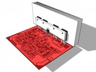
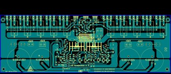
Excelent... despite i am not having free time to inspect in details
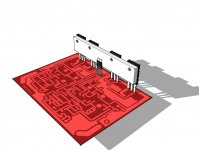
Seems you have joined all ground points to a single track... this is very good.
I could see a jumper... this is good too, because this way you made it better than use a long waving line around.
Thank you... i will give a check on that but gonna make is with calm... we have no hurry about...i gonna use new layout to November...so.... a lot of time we have to study things.
You have sent me strange gerbers.... i do think we need silk screen, copper tracks, drill holes and more two or three files (I have not knowledge about the stuff)... you sent me more than 20 files..hehehehe..... check if this is correct...i will send you some gerbers as example to you.
Thank you very much...but do it with calm, not needed to run this way...we will not use them now.
Please, inform your country and if possible update your profile including this information about you and more if you want... we will be glad to know you better.
regards,
Carlos
Last edited:
My pleasure
Seems you have joined all ground points to a single track... this is very good.
I could see a jumper... this is good too, because this way you made it better than use a long waving line around.
Thank you... i will give a check on that but gonna make is with calm... we have no hurry about...i gonna use new layout to November...so.... a lot of time we have to study things.
You have sent me strange gerbers.... i do think we need silk screen, copper tracks, drill holes and more two or three files (I have not knowledge about the stuff)... you sent me more than 20 files..hehehehe..... check if this is correct...i will send you some gerbers as example to you.
Thank you very much...but do it with calm, not needed to run this way...we will not use them now.
Please, inform your country and if possible update your profile including this information about you and more if you want... we will be glad to know you better.
regards,
Carlos
are you sure?Carlos, bigger boards will not increase price
Are there some PCB manufacturers that charge by the unit only and not by area?
- Status
- This old topic is closed. If you want to reopen this topic, contact a moderator using the "Report Post" button.
- Home
- Amplifiers
- Solid State
- Dx Blame MKIII Supercharged will soon be released