Hi Carlos, This new design looks really interesting, a new high powered amplifier from DX. This is really cool and we appreciate the time and effort you are spending to help us in our hobbies. I am a slow builder, I have just ordered the parts to build my two DX from Rudi's very good boards, so it will be a while before I get to this one.
I will report how they sound when finished.
Cheers and God bless you, John
I will report how they sound when finished.
Cheers and God bless you, John
Well dear John...i have to thank you by the confidence
and kindness.... Rudi boards are awsome.... he has passion for audio and is helping the Dx Corporation
We are not a real business, this "corporation" is just a game....in the real world it is an audiophile Union... the good ones are with us...other good ones will join us soon...the ones build a Dx amplifier become, automatically and immediatelly, a Dx Corporation Member, having the rigth to have their picture in the hall of fame and to receive updates, upgrades and special attention anytime and anywhere while using internet.
MSN, Skype, Facebook, Orkut, Yahoo messenger and anywhere and anytime, you may have help if needed, for free and in a gladly way...of course the main place is this forum, but there are other 8 foruns wide world, where i use to be in stand by mode, with the intention to give them support if needed.
Thank you very much, pictures of your amplifier, home, family, bicicle, motorcicle, audio appliances, dogs, cats, automobile, airplane, house, garden, and all stuff is wanted and will be extremelly appreciated..your own picture will be needed too, but send it together the authorization to use it or say clearly that you will not be happy to see it published...then your privacy will be respected.
My email adress is:
nanabrother@hotmail.com
Avoid the forum messenger, the PM ... it is very poor... we cannot attach videos, images or audios.... we have to use only links to uploaded material..go direct them i will be able to send all needed stuff.
regards,
Carlos
Last edited:
Destroyer,So, everybody that will buy must know 10 percent are included above the cost price
Your mistake was to use the phase "above the cost price" to explain away the extra 10%.
Instead you could have said +10% to defray some of the costs of getting the new design to the stage of "tested availability".
I am slowly doing something.... not very healthy i am these last weeks
But i am still moving a little.
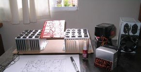
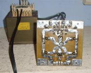
Working with the MKIII and also the MAKO prototype... assembling once again with separated heatsinks in order to avoid insulators... trying to scape from thermal resistance... wood bellow is what insulates one heatsink to the other..some transistors, for CCS purposes, are insulated, others are not.
Well boys..uncle charlie is doing something...slowly but doing.
MKIII will have boards available, also schematic and layout..about the MAKO i do not know what gonna happens...maybe boards in other forum...not sure about.
I have the obligation to test it into the power that was ordered... 500 watts RMS continuous, undistorted, over 4 ohms reactive load..unclipped signal with less than 0.005% THD... i will use two fans removing heat from these fins.... the amplifier will produce much more than that...but this depends on heatsinks size and fan blower applied.... the increase above the power agreed will be made by the one will spread the amplifier wide world.... i will be giving follow up and support during 1 year, so, doubts(about heatsink size, output power and power supply details (SMPS) will be solved after release.
The idea is 1 Kilowatt easy ... and much more distorted.... sadly i will not be able to guarantee the survival at 1 Kw because i am unable to test that... my supplies cannot reach that..also heatsinks...so..the informed power (minimum guaranteed power) will be 500 wiskies.
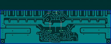
This is the input only...there are errors to fix...this is only the start..trying to do something "less ugly".
Boards will be produced by Alex mm.
regards,
Carlos
But i am still moving a little.
Working with the MKIII and also the MAKO prototype... assembling once again with separated heatsinks in order to avoid insulators... trying to scape from thermal resistance... wood bellow is what insulates one heatsink to the other..some transistors, for CCS purposes, are insulated, others are not.
Well boys..uncle charlie is doing something...slowly but doing.
MKIII will have boards available, also schematic and layout..about the MAKO i do not know what gonna happens...maybe boards in other forum...not sure about.
I have the obligation to test it into the power that was ordered... 500 watts RMS continuous, undistorted, over 4 ohms reactive load..unclipped signal with less than 0.005% THD... i will use two fans removing heat from these fins.... the amplifier will produce much more than that...but this depends on heatsinks size and fan blower applied.... the increase above the power agreed will be made by the one will spread the amplifier wide world.... i will be giving follow up and support during 1 year, so, doubts(about heatsink size, output power and power supply details (SMPS) will be solved after release.
The idea is 1 Kilowatt easy ... and much more distorted.... sadly i will not be able to guarantee the survival at 1 Kw because i am unable to test that... my supplies cannot reach that..also heatsinks...so..the informed power (minimum guaranteed power) will be 500 wiskies.
This is the input only...there are errors to fix...this is only the start..trying to do something "less ugly".
Boards will be produced by Alex mm.
regards,
Carlos
Attachments
Last edited:
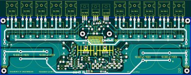
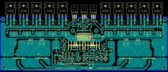
Here you have the MKIII, a new Dx Blame ST MKIII
This amplifier can operate with 1 ohm load.
Power is very good and you can see down the schematic.
No one is offering boards, or producing boards, it is free to whole world, not an exclusive design...my gift to my forum friends.
Board was not tested, but the circuit was assembled to check.... the board layout was produced by Alex mm and he may provide you material to produce your own boards, to etch them at home.
Enjoy and if you need anything just ask...also you can contact me in my personnal email adress, but i have to explain in advance that i am not selling and that i have no boards to offer...this is a diy design, an open source to the whole world enjoyment.
nanabrother@hotmail.com
regards,
Carlos
Attachments
I have these images provided by Doctor Alexandru
more images, black and with images to etch, then try Alex mm because i have not the tool to manipulate these images...my viewer is not working fine.
regards,
Carlos
more images, black and with images to etch, then try Alex mm because i have not the tool to manipulate these images...my viewer is not working fine.
regards,
Carlos
Attachments
Thank you Alex mm....good files dear Alexandru
Well Tekko, this shows to me you have made a good decision...the circuit is fine and was "cooked" a couple of monthes ago....well...it is a Blameless style, the best ones we can have now a days......so, go ahead with your own design or come aboard to the Corporation, join the good one that is yourself with the good ones from the Corporation, build the MKIII and give us the pleasure of your presence.
Was a coincidence...this happens and i am unable to read minds during your summertime (winter here)... also thomas is too much active and saturates my reception (C2sea)...please, take a look in the signature and please hit there andsubscribe tp the channel... then you will know uncle charlie better and you will see i use to be kidding.
regards,
Carlos
Last edited:
Very glad to see this circuit can be widely.
I studied this circuit, and test more than 30 version of the parts and different details. Has more than 6 years
I hope I can put my experience to share with you.
I have these little toys name L10 AMP, life for L20 AMP, L12-2 AMP.
Their father originated from one of the greatest English as a designer.
The three department amplifier output structure has different toys.
L10, 2 levels of EF. L20 level 3-2 2, EF L12 CFP level.
If you would like to I can send EMAIL to these SCH PCB research.
They each plate is I modify more than ten times. After a lot of instrument measurement I believe they will be of great reference value.
__________________
MY BBS;http://bbs.ljmaudio.net/
Last edited:
Member
Joined 2009
Paid Member
Alex's PCB looks good. With full 20kuf X 2 decoupling onboard , at least separate the input/IPS-VAS ground. Separate ground for all small signal references (CCS , DC cap , input filter and input signal ground) , connect to midpoint of "dirty" rail ground. speaker ground should also have a faston right next to the main earth connection (2 fastons). Center 2 faston grounds , + rail , - rail , and small signal ground reference should be dead center of the board and meet in a star. The input ground should be "lifted" with 4.7-10R from the small signal ground.
Don't need those 2 470uF-63v local decoupling caps since main (10Kuf) decoupling is already onboard. I do it a little different (below), but have my main decoupling on a separate board (separate PS PCB).
Circuit wise , very robust - high current MJE VAS and MJE drivers will drive 5 pair VERY well. AOK !!
OS
Attachments
But i am still moving a little.
Working with the MKIII and also the MAKO prototype... assembling once again with separated heatsinks in order to avoid insulators... trying to scape from thermal resistance... wood bellow is what insulates one heatsink to the other..some transistors, for CCS purposes, are insulated, others are not.
Well boys..uncle charlie is doing something...slowly but doing.
MKIII will have boards available, also schematic and layout..about the MAKO i do not know what gonna happens...maybe boards in other forum...not sure about.
I have the obligation to test it into the power that was ordered... 500 watts RMS continuous, undistorted, over 4 ohms reactive load..unclipped signal with less than 0.005% THD... i will use two fans removing heat from these fins.... the amplifier will produce much more than that...but this depends on heatsinks size and fan blower applied.... the increase above the power agreed will be made by the one will spread the amplifier wide world.... i will be giving follow up and support during 1 year, so, doubts(about heatsink size, output power and power supply details (SMPS) will be solved after release.
The idea is 1 Kilowatt easy ... and much more distorted.... sadly i will not be able to guarantee the survival at 1 Kw because i am unable to test that... my supplies cannot reach that..also heatsinks...so..the informed power (minimum guaranteed power) will be 500 wiskies.
This is the input only...there are errors to fix...this is only the start..trying to do something "less ugly".
Boards will be produced by Alex mm.
regards,
Carlos
This amplifier can operate with 1 ohm load.
Power is very good and you can see down the schematic.
No one is offering boards, or producing boards, it is free to whole world, not an exclusive design...my gift to my forum friends.
Board was not tested, but the circuit was assembled to check.... the board layout was produced by Alex mm and he may provide you material to produce your own boards, to etch them at home.
Enjoy and if you need anything just ask...also you can contact me in my personnal email adress, but i have to explain in advance that i am not selling and that i have no boards to offer...this is a diy design, an open source to the whole world enjoyment.
nanabrother@hotmail.com
regards,
Carlos
Carlos ,
Sorry to hear about your health and situation
 fantastic this new amplifier, this migh just be the "one" .....
")
All the best my friend ....
30 units are better than one Blameless unit to our forum and our community
dear Ljm_Ljm.... it is good to see you have researched into the good one.
This one is ready to go after long time of research and belong to a family, where they had progressive evolution... a Dx Corporation family (Union of nice audiophiles).... this has a history, a tradition... some kind of evolution in quality and power levels... has a destiny.
I do think it will be a very good idea you to open a thread about "My 30 Blameless variations, the evolution" and to post in a separate thread, your thread, these 30 amplifiers, each one of them with their schematic, comments, fourier graphics, AC graphics, voltage chart, current chart, pcboard layout, pictures of the units built ad review about each one of them...this will be a good cooperation to our people, to our forum, to the audiophiles and to the whole world..... you wlll add amplifiers in the place to suggest variations to mine one that is "ready to go"
Thank you very much, Dx Corporation feels honored by your offer but we decline as we want more options and not to change this one that will be keept the way it is unless appear a terrible mistake that may reduce reliability or impair the sonic quality.
regards,
Carlos
Well, thanks to all friend kindness, presence and support to the thread
Art M, John Geneva, A.wayne, Ostripper, Bigun, Tekko, Bigun, Andrew T and also to the silent readers... the ones that have read and have not posted comments.
The amplifier is simple, anything much different than the original Blameless with steróids.... no special solution, no custom design, just a variation around the same theme... sounds great as all Blameless amplifier does and was tested for your pleasure, enjoyment and safety.
regards,
Carlos
This is a very interesting. And very good structure.
Simple and its advantages. This will in we can repeat the desired results.
In this circuit, I have very much, and measurement of many of my friends use to listen to feel.
Sometimes we have to change it, and let the machine more suitable for yourself and friends listening habits.
This may not let I think sometimes I really should be put down the instrument to feel feel voice.
Although I in the test reached almost 0.000% THD 20 K
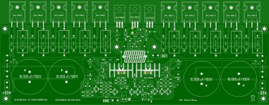
Alex MM, the PCB layout looks very good but I feel the ground trace is too thin to the -ve PSU caps.
I would make the board a bit deeper than 80mm, rotate input conn. and use star ground for I/P reference, add a separate spkr. ground lug - all just like ostripper's post #33.
Is the capacitor across Vbe multiplier 100uF or 100nF? Do you need rail clamp diodes on the speaker output?
but I feel the ground trace is too thin to the -ve PSU caps.I would make the board a bit deeper than 80mm, rotate input conn. and use star ground for I/P reference, add a separate spkr. ground lug - all just like ostripper's post #33.
Is the capacitor across Vbe multiplier 100uF or 100nF? Do you need rail clamp diodes on the speaker output?
Yes Prairiemystic... clamp diodes can be good
you can use them if you want.... the condenser is 100uF, but you can reduce till 22uf if you want, voltage there is very low, even a 6 volts condenser may fit.
Thank you very much dear harrydg... i would like to make your words mine..perfect answer to the provocation... that man will be ignored... wants to produce trouble..for sure he wants.. will go to the list of nasty bullies and there are some in the forum ... but there are few... this one already failed.
regards,
Carlos
Last edited:
PCB rev 2.0 ......
.... I have layout again same schematic , just 10 ohms resistor was aded , to separate the power ground from signal ground ........not so big change , but will se the diference in real life when amplifier will be start , and play the music
Regards Alex .
....
I have layout again same schematic , just 10 ohms resistor was aded , to separate the power ground from signal ground ........not so big change , but will se the diference in real life when amplifier will be start , and play the music Regards Alex .
Attachments
....
Regards Alex .
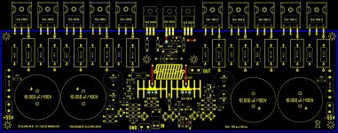
Yes , you will. No hum at all , won't know the amp is even on until the first "blast" hits you.
Proper power supply "etiquette" applies to integrated power amp supplies , too.
Stars , stars , and more stars ..... (below)
Perfection - good job , alex.
PS- -55 on +55V side ... just a typo.
OS
Attachments
Last edited:
- Status
- This old topic is closed. If you want to reopen this topic, contact a moderator using the "Report Post" button.
- Home
- Amplifiers
- Solid State
- Dx Blame MKIII Supercharged will soon be released