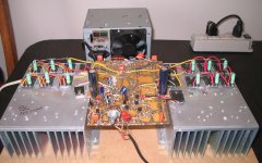
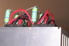
Here you have prototype assembled
A low power test.... soon i will make the high power test and will publish video...sorry by the quality, i am in a hurry and i cannot edit and spend time with it.
YouTube - Dx Blame MKIII low power test..real world test
regards,
Carlos
A low power test.... soon i will make the high power test and will publish video...sorry by the quality, i am in a hurry and i cannot edit and spend time with it.
YouTube - Dx Blame MKIII low power test..real world test
regards,
Carlos
OS, I hope you clean the flux off your boards and give them a varnish coating, those boards will ccorrode and look like crap otherwise after some time.
I'm betting that OS will have stolen the parts off that board for another project looooooog before there is any chance of corrosion setting in....

OS, I hope you clean the flux off your boards and give them a varnish coating, those boards will ccorrode and look like crap otherwise after some time.
That board is 2 years old. I have one 3 years old , too. Same lead/tin coating on 32 Year old altec-lansing power amp FR-4 PCB's was only slightly dull grey.
Tarnish on tin is a layer that will protect it for decades , just like aluminum.
Varnish and screen printing is good , but will not make for better sound or reliability. That FR-4 can NOT be burned (teflon composite !)
.....Flux don't matter on a PS board.
Anybody who etches alex's excellent work can just take waste solder-tin it , and their board will last 20+ years.
That is my "test power supply" - it has brought over 200 amps to life so farI'm betting that OS will have stolen the parts off that board for another project looooooog before there is any chance of corrosion setting in.
OS
I have found something different from the schematic
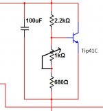
I have used other values into the bias circuit.... total resistance from base to emitter seems to be around 1200 ohms.
I have also used different transistor, a TIP41C that was in the front of my eyes in the junk box, watching me and asking me to be used..then it was installed (hehehehe).
I will check this better tomorrow, then i will use another transistor for bias, will try to find a plastic one that gonna be better, also the supply voltage will be different..then i gonna check the stuff with more precision.
For a while, if someone decide to assemble, them use 1K trimpot in series with 680 ohms resistor..this may work fine.
We gonna see the final value after further testings... also i need more power, more heat, to observe thermal drift... do not assemble for a while if you intend to do.. wait a couple of days please.
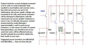
Also i want to check if will survive to 1 ohm.... calculations says yes..also simulator and transistor specification graphics...but real life test is the better way to know, or to have sure about....so.... wait a little because i will torture and will check heat in the CCS transistors and other details that must be checked.
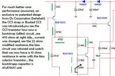
Maybe we gonna provide room in the board to the bootstrap as option...this way the guy can assemble one way or other way.
regards,
Carlos
I have used other values into the bias circuit.... total resistance from base to emitter seems to be around 1200 ohms.
I have also used different transistor, a TIP41C that was in the front of my eyes in the junk box, watching me and asking me to be used..then it was installed (hehehehe).
I will check this better tomorrow, then i will use another transistor for bias, will try to find a plastic one that gonna be better, also the supply voltage will be different..then i gonna check the stuff with more precision.
For a while, if someone decide to assemble, them use 1K trimpot in series with 680 ohms resistor..this may work fine.
We gonna see the final value after further testings... also i need more power, more heat, to observe thermal drift... do not assemble for a while if you intend to do.. wait a couple of days please.
Also i want to check if will survive to 1 ohm.... calculations says yes..also simulator and transistor specification graphics...but real life test is the better way to know, or to have sure about....so.... wait a little because i will torture and will check heat in the CCS transistors and other details that must be checked.
Maybe we gonna provide room in the board to the bootstrap as option...this way the guy can assemble one way or other way.
regards,
Carlos
Attachments
Last edited:
Sin duda hermano, no doubts dear Vargas
I have tested using 1.1 ohms....i could have something around 400 watts RMS.
It is a 150 watts at 8 ohms and go increasing power depending how huge is your supply.... i am uploading video and then you will have some more details...will take some time as i have to edit, trancode and encode into youtube.
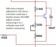
Final setup for bias is the image attached...be plugged into this thread..soon you gonna have the video link here.
regards,
Carlos
I have tested using 1.1 ohms....i could have something around 400 watts RMS.
It is a 150 watts at 8 ohms and go increasing power depending how huge is your supply.... i am uploading video and then you will have some more details...will take some time as i have to edit, trancode and encode into youtube.
Final setup for bias is the image attached...be plugged into this thread..soon you gonna have the video link here.
regards,
Carlos
Attachments
Here you have the video with some comments and some specifications
obtained during tests using simple instruments..my scope is damaged, so i cannot check it using scope..only simulator and playback tests.
YouTube - Dx Blame MKIII test using 550VA power supply
regards,
Carlos
obtained during tests using simple instruments..my scope is damaged, so i cannot check it using scope..only simulator and playback tests.
YouTube - Dx Blame MKIII test using 550VA power supply
regards,
Carlos
Attachments
Good amp.
I know , I am listening to one now.
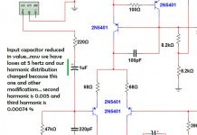
Alex forgot the input LPF resistor (next to the 220pF) to ground in his last post (just saw that).
An amp like yours should do way more than 250w/8R , that little test power supply in my last post will drive a blameless with just 2 pair MJL to over 180w/4R (45-0-45vdc). At 70V+ , your amp will still be perfectly in spec (the JOY of current sources), and you will have 400w/8R (peaks) to enjoy.
I use the 500R bias pot, too. 325 ohm to get 50ma w/.22R OP resistors. Vbe transistors do compensate differently. 2sc3503 almost is perfect with MJE/MJL output stage with 2.2k/680/500 resistor combo. You can change Vbe ratio with (3.3K/1.2k/500R) , this will make the transistor more in control of the compensation (might overcompensate). If your transistor has less Vbe, a higher resistor combo might make it just right.
OS
I know , I am listening to one now.
Alex forgot the input LPF resistor (next to the 220pF) to ground in his last post (just saw that).
An amp like yours should do way more than 250w/8R , that little test power supply in my last post will drive a blameless with just 2 pair MJL to over 180w/4R (45-0-45vdc). At 70V+ , your amp will still be perfectly in spec (the JOY of current sources), and you will have 400w/8R (peaks) to enjoy.
I use the 500R bias pot, too. 325 ohm to get 50ma w/.22R OP resistors. Vbe transistors do compensate differently. 2sc3503 almost is perfect with MJE/MJL output stage with 2.2k/680/500 resistor combo. You can change Vbe ratio with (3.3K/1.2k/500R) , this will make the transistor more in control of the compensation (might overcompensate). If your transistor has less Vbe, a higher resistor combo might make it just right.
OS
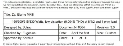
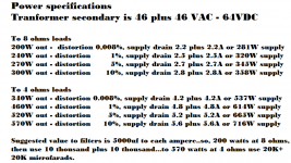
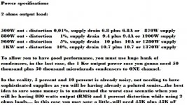
MKIII specifications from the simulator and power supply requirements
The video explains in details... there are two parts...here you have the link to part 1:
YouTube - MKIII amplifier, specs. and power supply requirements - part ONE
regards,
Carlos
The video explains in details... there are two parts...here you have the link to part 1:
YouTube - MKIII amplifier, specs. and power supply requirements - part ONE
regards,
Carlos
MKIII specifications from simulator and power supply requirements
Part two:
YouTube - MKIII amplifier, specs. and power supply requirements - part TWO
regards,
Carlos
Part two:
YouTube - MKIII amplifier, specs. and power supply requirements - part TWO
regards,
Carlos
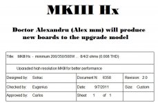
MKIII Hx model was the result of some tuning made
Now sonics are the best possible to this schematic, Alexandru will prepare new boards as i have made some changes, and they are described in the images you will see attached.
regards,
Carlos
Now sonics are the best possible to this schematic, Alexandru will prepare new boards as i have made some changes, and they are described in the images you will see attached.
regards,
Carlos
Attachments
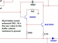

Here you have more realistic values to the bias control
Schematic attached,
The circuit was tested naturally, as it was tuned listening.
regards,
Carlos
Schematic attached,
The circuit was tested naturally, as it was tuned listening.
regards,
Carlos
Attachments
Last edited:
Hx is a hair raising amplifier.... produces strong emotions
YouTube - Hx is fast, a very precise audio amplifier
The prototype is ugly, but sonics are beautifull.
regards,
Carlos
YouTube - Hx is fast, a very precise audio amplifier
The prototype is ugly, but sonics are beautifull.
regards,
Carlos
Attachments
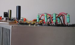
I like the vertical emitter resistors.
Makes the assembly look like playing 3D chess. Not I could ever cope with playing 3D chess.
The component values in this latest schematic are starting to resemble good design.
Am I allowed to suggest a few minor adjustments that might result in further improvement in sound quality.
Makes the assembly look like playing 3D chess. Not I could ever cope with playing 3D chess.
The component values in this latest schematic are starting to resemble good design.
Am I allowed to suggest a few minor adjustments that might result in further improvement in sound quality.
Come on!Am I allowed to suggest
Who will forbid you, AndrewT?
Is there anyone who can or will stop a good suggestion?
- Status
- This old topic is closed. If you want to reopen this topic, contact a moderator using the "Report Post" button.
- Home
- Amplifiers
- Solid State
- Dx Blame MKIII Supercharged will soon be released