Hi Dado,
1. Can I use 0.15 ohms for R30, R31, R93, R96 ?
2. Is there some component that I should sort ?
Nicola
Hi Nicola,
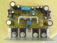
You can use 0.15ohm for those resistors. I made it of the six parallel 1ohm/0.5W resistors, look at the photo, only one set was mounted(right side).
By sorting I suppose you meant matching. I did match hfe for the LTP and current mirror transistors using ordinary universal meter with hfe feature. Output transistors and drivers were from the same batch and used them with no matching. You can match as follows:
Q2-Q3 LTP(glued together- or use thermotube)
Q5-Q6 CM
Q94-Q95 drivers
Q8, Q10, Q96, Q97 output trs.
Dado
Attachments
1. Why did you glue Q2 and Q3 together?
2. I asked about matching (not sorting...) in order to buy quantity of transistors before building, but I don't know how to do the practical work of matching.
Nicola
Q2 and Q3 were glued together to keep the temperature equal and thus lessen fluctuation of the DC output voltage on the output. It is not to critical, you can keep them separated if you like.
About matching you can find a lot of explanation even in this forum by searching. You can look here too:
Matching Power and Driver Transistors
I used ordinary multimeter with hfe feature.
Dado
Hi Dado,
Should I isolate electrically output transistors from L bar ?
Are the four screws for output transistors enough to maintain the board to L bar ?
Nicola
Yes you should do that, use mica insulation pads and thermal paste, or silicon pads.
I think it is called TO-3P.
If you look at the photo in #141 you can see two screws fixed from bellow. I do it first and then fix the transistors.
Dado
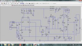
I couldn’t resist but to try catalin http://www.diyaudio.com/forums/solid-state/135122-wonderfull-sziklai-21.html#post3183355suggestion to move compensation capacitance from the collector to the emitter of the LTP transistor.
Easiest way to tray that was this amp with the TMC.
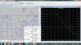
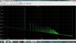
Here are simulations, it is possible to use smaller TMC capacitances and get good phase and gain margin. THD20k dropped from 0.000696% to 0.000249%. LTP emitter resistors are increased to the 220R, tail current increased by 50% and VAS local NFB removed.
I am listening now this modified amp and I like the sound very much, for such simple amp it is amazing.
dado
Easiest way to tray that was this amp with the TMC.
Here are simulations, it is possible to use smaller TMC capacitances and get good phase and gain margin. THD20k dropped from 0.000696% to 0.000249%. LTP emitter resistors are increased to the 220R, tail current increased by 50% and VAS local NFB removed.
I am listening now this modified amp and I like the sound very much, for such simple amp it is amazing.
dado
Attachments
Andrew the compensation is moved not the feedback.
Its an old trick, youd probably get the same result returning the compensation to the base of inverting input.
Good result though, interesting stuff Dado.
Yes homemodder I now about that old trick, but I couldn't get stable simulation with close enough distortion, so I gave up with it and never triad it in real circuit.
dado
The issue is whether you get the same distortion figure with the same phase margin. In any amp compensation can be reduced for lower distortion but less stability results, thats not a good comparison.
Agree, I did it with similar phase and gain margin.
I checked compared with post 1 and thats why I found good result, have you tried with the cascoded amp ??
Cascoded LTP or cascoded VAS?
The hawksford cascoded vas.
Yes I tried with my TT amp but not with so good result. It could be that distortion was already so low (simulated) that improvement is not obvious. http://www.diyaudio.com/forums/solid-state/216780-tt-amp-200w-8ohm-701w-2ohm-7.html#post3187875
- Home
- Amplifiers
- Solid State
- bootstrapsCCS+T-TMC