Hi Dado,
A. About other capacitors not electrolytics. Is the quality not significative for some of them (like the green C4) for example ?
B. I see the central thermal aluminium you use to cold Q94 and Q95 :
B1. Is this main dissipator DIY or available somewhere ?
B2. You have added an additional piece of metal to it.. Are Q94 and Q95 so hot ?
Have a nice day!
Nicola
A. C13 and C22 are mica, C23 is ceramic COG/NPO, and all others non electrolytic are polypropylene film/foil type.
B. Heathsink for Q94, Q95 I made from alu breaket 10x40mm 2mm thickness and main alu breaket used for output transistor is 30x50mm 3mm thickness.
B1. I did not find suitable heathsink here in Croatia and I like to make all what is possible by myself.
B2. Yes it is quite hot 50 degree C max and I made this heathsink longer(90mm) on last PCB layout because of that.
here is new corrected bill of materials.
cheers, dado
Attachments
Good morning, Dado!
For amp :
Can I replace C2 mica with polystyrene ?
For power supply :
a. How many VA should I count for the transformer ?
b. Is C1 capacitor X2 type ?
c. Long life 50V type for C2 & C3, and low ESR for other C4-C9 ?
d. Is voltage for C4-C9 50V too ?
e. For R1, R4, R5, which power handling ?
f. For C10 & C11 the best I can find, like paper oil or MKP ?
Nicola
Good morning, Dado!
For amp :
Can I replace C2 mica with polystyrene ?
For power supply :
a. How many VA should I count for the transformer ?
b. Is C1 capacitor X2 type ?
c. Long life 50V type for C2 & C3, and low ESR for other C4-C9 ?
d. Is voltage for C4-C9 50V too ?
e. For R1, R4, R5, which power handling ?
f. For C10 & C11 the best I can find, like paper oil or MKP ?
Nicola
For amp :
Can I replace C2 mica with polystyrene ?
Yes, even for C13 and C22 you can use polystirene if you can find as that is best type of all.
For power supply :
a. How many VA should I count for the transformer ?
I used 400VA for stereo. For dual mono 2x250VA or 2x300VA will be good.
There is no to much in transformers power.
b. Is C1 capacitor X2 type ?
No need, this is low voltage side of transformer. If you use a capacitor connected to 240V side, as one connected parallel to power switch then use X2 type.
c. Long life 50V type for C2 & C3, and low ESR for other C4-C9 ?
OK
d. Is voltage for C4-C9 50V too ?
Better use 63V for C2 and C3 and for the rest 50V is OK.
e. For R1, R4, R5, which power handling ?
f. For C10 & C11 the best I can find, like paper oil or MKP ?
MKP is OK, no need to pay stiff price for paper in oil, but you can use it off cource.
dado
For amp:
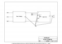
Could you please verify where I set the returns (ground) points for speaker output and input cable (see photo below) ?
For power supply:
Which type for C1 ?
What effect for C1 and R1 ? Are they mandatory ?
I'll use 0.25W for all resistors, but 5W for R2 & R3, OK ?
Could you please verify where I set the returns (ground) points for speaker output and input cable (see photo below) ?
For power supply:
Which type for C1 ?
What effect for C1 and R1 ? Are they mandatory ?
I'll use 0.25W for all resistors, but 5W for R2 & R3, OK ?
Attachments
For amp:
Could you please verify where I set the returns (ground) points for speaker output and input cable (see photo below) ?
For power supply:
Which type for C1 ?
What effect for C1 and R1 ? Are they mandatory ?
I'll use 0.25W for all resistors, but 5W for R2 & R3, OK ?
C1 and R1 are not mandatory, they help to tame rectifiers noise, any tipe for C1 is OK(polyester).
Yes R2 and R3 are only 5W resistors here.
Regarding the ground connection I will prepare a block diagram of it asap. This is quite important to avoid ground loop and prevent the buzz from 50Hz to enter the amp.
Do you need gerber files for PCBs?
dado
I finished to check layout components with BOM and schema. All is OK. I just noticed R25 is there, but not marked as R25 in both schema and layout. That's all...
About ground loops, I experimented them in my current system when building JLH 80W... I'm very attentive to this chapter and your own experience! I'm reading deeper your block diagram this evening.
Yes, it would be very good to have gerber files to produce the PCBs.
Nicola
About ground loops, I experimented them in my current system when building JLH 80W... I'm very attentive to this chapter and your own experience! I'm reading deeper your block diagram this evening.
Yes, it would be very good to have gerber files to produce the PCBs.
Nicola
Hi Dado,
My mistake for R25. This resistor is written R without number on schema dated 19.09.2011 01:37 PM, but shown in layout (dated 19.09.2011 02:05 PM.)
R28 is shown on layout, but without number (same layout).
You say invert Q10 and Q97, but they seem correct (same layout).
OK for warning. Thanks!
Nicola

Hi Dado,
I’ve located the main parts for the amp, but not for the power supply (capacitor models still under study). So order is still not completed.
What do you think of doubling the values, and replacing the 5W resistors with selfs for the PSU?
Nicola
You can double the capacitors value, but I think there is no need, specially if you do dual mono. I used Elna LP5 63V quite cheap but good. If you double the value you go in to inrush current area, and need to limit it.
"replacing the 5W resistors with selfs " sorry I don't understand what you whant to say.
Dado
Hi, Dado
Sorry, 'self' is the french word. I mean inductance. I read that some schemes have inductance at this place, with notably improved results.
For the capacitors, I'll try with your values first.
Thanks for Elna reference.
Nicola
Yes you can use an inductance, that should be even better. I did not try it as it should be as much mH as possible and could be cumbersome. You can increase the resistors too, but not to much as you loose voltage there and need more wattage.
Dado
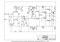
Here is a suggestion to try something. The new schematic shows R24//C23 connected to the emitter of the Q95 instead to the collector of the Q9. This should render a bit lower distortion as will not load the VAS. I simulated it only, no listening was done.
Dado
Dado
Attachments
There's a hint of Leach in that feedback.
This is actually manipulation with open loop bandwidth but traying to lessen disadvantages when this resistor was parallel to Miller compensation capacitor and in this case TMC.
Dado
- Home
- Amplifiers
- Solid State
- bootstrapsCCS+T-TMC