I must have been too indirect - that is nearly the opposite conclusion from how I interpret the research, theory, practice
there are several distortion mechanisms that rise with frequency - in fact they cause rising phase shift nonlinearity with frequency too - independent of loop gain slope - so for flat loop gain amps the distortion does rise with frequency
with higher loop gain the distortion rises to the same level that it gets to with the same amp "flat loop gain compensated" - but the distortion at all frequencies below the corner is lower
I would point to Self, Cordell and even our low/"no" feedback designers like Pass and Curl here to suggest that the output stage looks pretty feeble - even at 100 W parallel output devices are a good idea for multidriver dynamic loudspeaker with possible 2 Ohm impedance dips due to bad XO design
and triple EF seems like a requirement to avoid load impedance and Q beta nonlinearity from limiting VAS performance
when those measures are in place I think the "back emf"/complex load arguments are way less relevant
I have understood your argument about cutting loop gain at audio frequencies, and I followed all that discussion before, but I could not help myself but to try it and hear how it sounds.
I do not think there is any benefit that I can hear, but some higher distortion at lower frequences is no big deal. I was trying to get decreasing harmonics in the FFT(simulated only).
Triple EF, parallel output devices, that is all an another story. I wanted simple and good sounding amp.
Did you meant triple EF by this??I would consider guarding/shielding the mirror out/VAS buffer end node just to maximize loop gain
dado
I consider critical subjective evaluation too difficult – you absolutely need two complete amps with only the one tested variable different between them, level matching, A/B/X and a number of subjects improve the reliability – without that level of care I would dismiss even my own “just listen” opinions as worthless for informing engineering design
guarding is a layout technique that put a low impedance trace between a sensitive node and a "aggressor" node that has signal we want to keep out ot the sensitive node
the low impedance trace preferably follows the signal on the sensitive node to prevent its (larger) parasitic leakage impedances to the sensitive node from being a problem
given the high sensitivity of the 2-pole response to small pF C, MOhm "bridge" impedances I would consider guarding/shielding the mirror-VAS input buffer node from the VAS out/amp output node's large Vswing
as for Lateral Mosfets - what they are missing is Gain - gm
for reduced VAS load they only look good at low frequencies - at high audio frequency the incompletely bootstrapped Cgs becomes a significant load
Last edited:
having worked with speakers i know that our hearing is particularly sensitive to the phase content...so when it comes to base performance of tubes h2 may be the reason, but another could be the low end phase shift that starts an octave or two above the actual low end cutoff frequency...this being trafos or coupling caps.. I agree that good tube amps excel in base performance over most SS equipment
if the effect is real and its just frequency response of coupling networks then SS amps can be EQed - likewise output impedance can be padded to match
in fact that is what Bob Carver did in the Carver-Stereophile Challenge
with their own source, speakers, in their own listening room Stereophile's "Golden Eared" reviewers couldn't tell Bob's $600 SS amp from their own choice of "SOTA" tube amp after Bob tweaked the SS amp frequency response, output impedance for a deep null with the tube amp
I consider critical subjective evaluation too difficult – you absolutely need two complete amps with only the one tested variable different between them, level matching, A/B/X and a number of subjects improve the reliability – without that level of care I would dismiss even my own “just listen” opinions as worthless for informing engineering design
guarding is a layout technique that put a low impedance trace between a sensitive node and a "aggressor" node that has signal we want to keep out ot the sensitive node
the low impedance trace preferably follows the signal on the sensitive node to prevent its (larger) parasitic leakage impedances to the sensitive node from being a problem
given the high sensitivity of the 2-pole response to small pF C, MOhm "bridge" impedances I would consider guarding/shielding the mirror-VAS input buffer node from the VAS out/amp output node's large Vswing
as for Lateral Mosfets - what they are missing is Gain - gm
for reduced VAS load they only look good at low frequencies - at high audio frequency the incompletely bootstrapped Cgs becomes a significant load
I agree completely with you about subjective evaluation, and now I am in no possibility to do proper listening test.
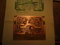
I included PCB in this tread in the begining and I would appreciate your comments.
I am not sure I understand this, do you mean it's better to use TPC instead of TMC??given the high sensitivity of the 2-pole response to small pF C, MOhm "bridge" impedances I would consider guarding/shielding the mirror-VAS input buffer node from the VAS out/amp output node's large Vswing
One other thing, I downloaded SPICE models from Supertex, but LTspice doesn't recognize it. I used NJFET from LTspice librery for temporary test.
Here is my LTspice zip file.
dado
Attachments
If you try to make speakers linear in the crossover region that area will stand out...so you need a suck-out in that area to have the speaker sound natural...my understanding of this is that our hearing is quite sensitive for multi source multiphase SPL...also testing raw drivers reveals this, as you can't actually tell the SPL curve by listening, as what you feel is loud actually measure quite low and the and the opposite what you hear as gentile can in fact have high SPL...much more to speakers than SPL linearity and distortion..
This reminds me of Baxandall's test set up for comparing amplifiers.if the effect is real and its just frequency response of coupling networks then SS amps can be EQed - likewise output impedance can be padded to match
in fact that is what Bob Carver did in the Carver-Stereophile Challenge
with their own source, speakers, in their own listening room Stereophile's "Golden Eared" reviewers couldn't tell Bob's $600 SS amp from their own choice of "SOTA" tube amp after Bob tweaked the SS amp frequency response, output impedance for a deep null with the tube amp
I prefer 2-pole compensation on theory/simulation grounds – I’ve not built comparable hardware - composite op amp circuits are more my current style - analyzing, simulating discrete power amps is more an intellectual exercise for me
I believe it was finally accepted in the Cordell Book thread TMC debate that my linear stability analysis sims showed no advantage to TMC vs 2-pole – and that the loop gain cross section for useful stability analysis has to measure the gain around the output Q inside the local TMC loop http://www.diyaudio.com/forums/soli...lls-power-amplifier-book-134.html#post2420438
There also appears to be little to choose between them in simulated clipping response when values are adjusted for the same total loop gain enclosing the output Q
Since there is a fairly large linearizing effect on the input diff pair with 2-pole’s larger loop gain giving much smaller input error signal I would choose 2-pole over TMC with what I think I know about the two options
Last edited:
David, this is semantics, superficial nonsense. You know as well as I do that damping factor is the ratio of load to source impedance.
Maybe my post was not clear - I was actually agreeing with your POV
I was trying to make the point that high damping factor might result in a badly damped system i.e. with Q >0.7.Again, you know well that SETs inject a great deal of H2 and that this is indeed enjoyed by many audiophiles. Adding some output resistance simply hikes up output impedance, lowering damping factor and achieving precisely what I was alluding to.
I don't remember any crafty negotiation, although my receipt from April 2002 does have the kit price of AU$420 crossed out and $213 written there instead. Sorry if you feel bitter about this. I don't have any feelings of guilt about the deal, but maybe I just have a poor memory.You mustn't kick yourself for your apparent 'poor judgement' buying the AKSA, which you obtained by crafty negotation anyway. I would hope you sold it for a good price! This is a cheap shot, and completely unsolicited.
I really enjoyed owning the AKSA and it met its promise of sounding "valvelike". I still own a P61 and although it's not as good as the 100N it shares the same characteristics of sounding warm and engaging. IMO where both these amps lose out is when trying to follow busy music and complex rhythms.
Please let me stress that this is only my opinion and readers are at liberty to assume I'm wrong/foolish/lying or whatever else they choose.
By the way I never got attacked by NP for suggesting my Aleph 30 is very boring to listen to. This really is an amp that is hopeless with rhythms IMHO.
More gratuitous criticism, really, why don't you use the forum for its intended purpose, to swap information of genuine use to other people?
Hugh
Sorry if you thought my "ported" comment was aimed specifically at your speakers. FWIW I also use ported speakers and I know that theoretically they have poor transient response at LF. I am working on a new project to sidestep this.
There seems to be an unwritten rule on this forum that nobody shall criticise the sound of any equipment. I actually value people's subjective comments (although it is nigh on impossible to judge if these people share your own perspectives) and regard reasonable criticism as of "genuine use".
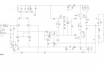
TPC now
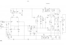
I simulated the same schematic, but with 2-pole compensation.
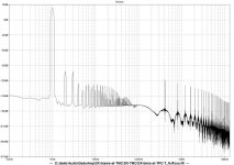
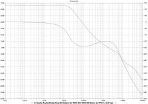
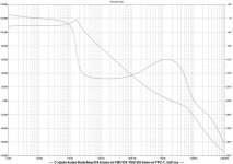
Schematic, FFT, OLG with R//C and OLG without R//C.
distortion at 1kHz
Fourier components of V(vout)
DC component:0.00057103
Harmonic Frequency Fourier Normalized Phase Normalized
Number [Hz] Component Component [degree] Phase [deg]
1 1.000e+03 2.134e+01 1.000e+00 -0.02° 0.00°
2 2.000e+03 1.189e-05 5.573e-07 100.11° 100.12°
3 3.000e+03 1.109e-05 5.195e-07 16.99° 17.01°
4 4.000e+03 6.457e-07 3.025e-08 95.53° 95.55°
5 5.000e+03 1.175e-07 5.508e-09 -71.57° -71.55°
6 6.000e+03 4.228e-07 1.981e-08 90.47° 90.49°
7 7.000e+03 8.708e-07 4.081e-08 22.50° 22.52°
8 8.000e+03 2.746e-07 1.287e-08 64.52° 64.54°
9 9.000e+03 9.066e-07 4.248e-08 27.06° 27.08°
Total Harmonic Distortion: 0.000077%
On next PCB I will make provision for both TMC and TPC and then I can compare!!
dado
I simulated the same schematic, but with 2-pole compensation.
Schematic, FFT, OLG with R//C and OLG without R//C.
distortion at 1kHz
Fourier components of V(vout)
DC component:0.00057103
Harmonic Frequency Fourier Normalized Phase Normalized
Number [Hz] Component Component [degree] Phase [deg]
1 1.000e+03 2.134e+01 1.000e+00 -0.02° 0.00°
2 2.000e+03 1.189e-05 5.573e-07 100.11° 100.12°
3 3.000e+03 1.109e-05 5.195e-07 16.99° 17.01°
4 4.000e+03 6.457e-07 3.025e-08 95.53° 95.55°
5 5.000e+03 1.175e-07 5.508e-09 -71.57° -71.55°
6 6.000e+03 4.228e-07 1.981e-08 90.47° 90.49°
7 7.000e+03 8.708e-07 4.081e-08 22.50° 22.52°
8 8.000e+03 2.746e-07 1.287e-08 64.52° 64.54°
9 9.000e+03 9.066e-07 4.248e-08 27.06° 27.08°
Total Harmonic Distortion: 0.000077%
On next PCB I will make provision for both TMC and TPC and then I can compare!!
dado
Attachments
Question for Hugh and OS!
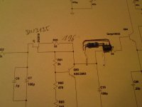
You probably notice tha I use local feedback on VAS, that bridge over TMC(1meg//5pF).
It decreases open loop gain at low frequences from more then 100dB to litle less then 60dB and kip it up to 30kHz.
Some says that there is no benefit in it, but I coud not resist but to tray it.
What is you oppinion??
dado
I was listening this amp each day and the sound is so good that I think it is the best amp of all I made. I am not sure what part is doing good, the bootstrap CCS or constant OLG.
Next in my list I am going to bild, is similar amp but with two output pairs, capacitance multiplier and possibility to simple insert/remove local VAS feedback (rsistor//capacitor).
I am amazed how such simple amp could sound good. Bass is fantastic, and for mid and treble no complains whatsoever.
dado
Attachments

![DADO-T-TMC-2pairs.LAY].png](/community/data/attachments/204/204160-ecf2491254d05081dc2f0a5976172e55.jpg)
![DADO-T-TMC-2pairs.LAY].png](/community/data/attachments/208/208344-25b458c3cb25581fca649d270dda1df4.jpg)
Hi,
returning to the phase & gain plot in post1.
The phase margin @ ~2.3MHz is ~60degrees (gain = +0dB).
The phase margin @ 100kHz is ~ 25degrees (gain = +38dB).
How do these phase margins compare with an "unconditionally stable amplifier"?
Is that dip in phase margin around 100kHz, what is called "conditional stability"?
...
Is that dip in phase margin around 100kHz, what is called "conditional stability"?
yes higher order slope compensation schemes move towards the conditional stability region - but unless the phase margin dips below 0 then the loop doesn't actually support nonlinear oscillation
to oscillate you need to meet both the 180 degree phase shift and the gain = 1 conditions - Burr Brown's Graeme suggested calling it "gain stabilized" when the gain was large in the region of low phase margin
for tube amps it was a big problem because the gain slowly rises at turn on and sweeps the loop gain through the conditionally stable region
with solid state amps the gain is usually established within a small fraction of the potential conditionally (un)stable frequency
again to get oscillation you need both 0 phase margin and gain reduction to == 1
clipping is one way to get "gain reduction" - describing function analysis can be useful to us simple minded SISO "Classical" Bode theory based designers
the thing to look at is clipping recovery - the low phase margin at lower frequency may indicate ringing/sticking/poor recovery
when TPC, TMC component values are adjusted for the same loop gain as measured inside both loops, around the output Q then the stability/recovery behaviors look very similar
I have built composite op amp circuits with a region of 3rd order loop gain slope which do cross 0 phase margin at intermediate frequencies - if some of the gain comes from positive feedback involving the output stage then when the output stage clips the excess loop gain and phase shift both decrease on output clipping and the amp can be stable in clipping
slew rate limiting can also result in describing function gain reduction and some of my 3rd order loop gain protypes did have oscillations with slow slewing input op amps - not an issue with discrete design
Last edited:
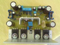
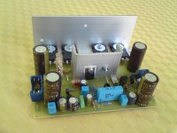
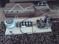
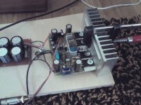
first listening
I finished one chanell and power supply. I did same measurement of the bias current against temperature. I started with 20mV on 0.16ohm of the emiter resistor. As drivers are on separate heathsink, and bias spreader is on main heathsik together with output transistors, it settled its temperature faster. The bias current first increased to 25mV and then decreased to 19-20mV after output transistor reached cca 50 degree Celsius.
I could not resist but to connect it and did first listening.
I am very very pleased with result and I will come latter with more measuring and listenig when I finished second channel
dado
Attachments
- Home
- Amplifiers
- Solid State
- bootstrapsCCS+T-TMC