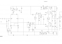
then use the same style as the rest of the schematic for quoting component value.
4M7 cannot be confused for 47meg
Sorry that is how LTspice is doing schematics.
dado
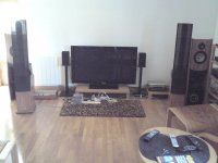
Listening in Stereo
Finilly I finished second channel and a listening in Stereo could start.
I was so eager to start with a listening that I adjusted the quiescent bias current only and started with listening.
I set the quiescent current to 120mA per pair(20mV/0.16ohm).
No thump at switch on and there was total silence from a loudspeakers even when I put my ear close to woofer or twitter.
The sound, for me is no easy to evaluate my own work, but it was all I expected.
Bass is very deep, punchy and fast(I use closed box for woofer).
Midle and high is crystal clear, violins so natural, female voice with no sibilance.
I used SACD, ordinary CD and XRCD during my whole day of the listening.
I would like someone else to make this amp and to have others opinion.
For interested I will add PCB pdf files, just ask.
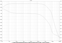
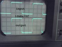
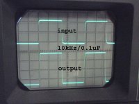
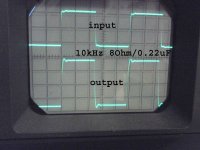
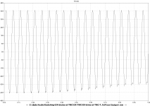
Tomorow I will do some measuring tests with sinus, triangle and square wave on 8ohm and 4ohm, paralled to different capacitance.
No distortion tests as I do not have equipment yet, but how amp sounds must be close to the simulated results, and no stability problem at all.
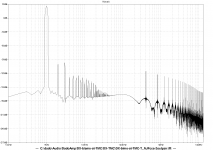
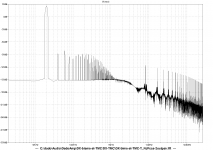
attached are CLG, 1kHz and, 20kHz FFT simulated of course.
dado
Finilly I finished second channel and a listening in Stereo could start.
I was so eager to start with a listening that I adjusted the quiescent bias current only and started with listening.
I set the quiescent current to 120mA per pair(20mV/0.16ohm).
No thump at switch on and there was total silence from a loudspeakers even when I put my ear close to woofer or twitter.
The sound, for me is no easy to evaluate my own work, but it was all I expected.
Bass is very deep, punchy and fast(I use closed box for woofer).
Midle and high is crystal clear, violins so natural, female voice with no sibilance.
I used SACD, ordinary CD and XRCD during my whole day of the listening.
I would like someone else to make this amp and to have others opinion.
For interested I will add PCB pdf files, just ask.
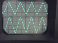
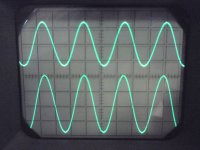
Tomorow I will do some measuring tests with sinus, triangle and square wave on 8ohm and 4ohm, paralled to different capacitance.
No distortion tests as I do not have equipment yet, but how amp sounds must be close to the simulated results, and no stability problem at all.
attached are CLG, 1kHz and, 20kHz FFT simulated of course.
dado
Attachments
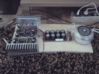
Lab measurements
Some technical data:
power supply: 400VA trensformer, +-46V, 2x23000uF
power on 8ohm 105W before clipping
power on 4ohm 170w before clipping
gain 32dB with -3dB from 5Hz to 560kHz
input resistance cca. 33kohm
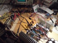
Here are some photos from test measurement.
dado
Some technical data:
power supply: 400VA trensformer, +-46V, 2x23000uF
power on 8ohm 105W before clipping
power on 4ohm 170w before clipping
gain 32dB with -3dB from 5Hz to 560kHz
input resistance cca. 33kohm
Here are some photos from test measurement.
dado
Attachments
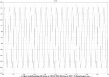
I noticed strange behavior durin simulation with 20Hz close to clipping.
The reson was in capacitance multipliers. I changed R26, R29 from 1kohm to 100ohm and R27, R28 from 33kohm to 10kohm and all was OK after that.
It looks that the capacitors connected to multiplying trensistors were loaded to slowly trough 1kohm. That manifested itself only at very low frequencies.
First diagram is with old multipliers.
dado
Attachments
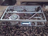
A box skeleton finished and populated. Made from aluminum L profiles. Now I have to cover it with wood. This is now integrated amp with 3 inputs and I am making it for my dougther.
I like the sound more and more each time I am listening to it. It is pity no one whants to make this amp, I would like to hear ther opinions. It is simple and very stable.
dado
I like the sound more and more each time I am listening to it. It is pity no one whants to make this amp, I would like to hear ther opinions. It is simple and very stable.
dado
Attachments
Member
Joined 2009
Paid Member
Dadod, I like this bootstrapped CCS approach (I simulated an all-BJT version earlier this year for a low voltage tube-SS hybrid) but it never made it onto the bench. I'm now thinking it might be a good solution for my JLH amplifier where I don't want to give up the bootstrap topology from the original design but at the same time I need a CCS to kill any chance of thermal runaway of the idle current in the output - do you think it would work in this way ?
Last edited:
Dadod, I like this bootstrapped CCS approach (I simulated an all-BJT version earlier this year for a low voltage tube-SS hybrid) but it never made it onto the bench. I'm now thinking it might be a good solution for my JLH amplifier where I don't want to give up the bootstrap topology from the original design but at the same time I need a CCS to kill any chance of thermal runaway of the idle current in the output - do you think it would work in this way ?
I am not sure which one of JLH amps you are referring to, but this kind of CCS it's easy to use with bootstrapp. CCS will not prevent thermal runaway, it will make the VAS current to fluctuate less with the signal. To prevent thermal runaway you need some kind of a bias spreader, but you know that already.
dado
Member
Joined 2009
Paid Member
The version is the JLH 1969. In this design there are no emitter resistors on the output devices or provide local feedback in the case of temperature rise increasing idle current. The current is also sensitive to the rail voltage so mains AC fluctuations can move the operating point away from where it should be. I thought a CCS would help greatly to address this issue because the output stage can't draw more current than the CCS allows it to. Unfortunately, I suspect a plain CCS without bootstrap may take away something good from the 'sound'.
Thinking about it further, I'm not sure that what you have used retains enough influence of the bootstrap on the current through the VAS to make it sound the same as a regular bootstrap.
Thinking about it further, I'm not sure that what you have used retains enough influence of the bootstrap on the current through the VAS to make it sound the same as a regular bootstrap.
The version is the JLH 1969. In this design there are no emitter resistors on the output devices or provide local feedback in the case of temperature rise increasing idle current. The current is also sensitive to the rail voltage so mains AC fluctuations can move the operating point away from where it should be. I thought a CCS would help greatly to address this issue because the output stage can't draw more current than the CCS allows it to. Unfortunately, I suspect a plain CCS without bootstrap may take away something good from the 'sound'.
Thinking about it further, I'm not sure that what you have used retains enough influence of the bootstrap on the current through the VAS to make it sound the same as a regular bootstrap.
You mean 10W A class JLH amp probably
You have to experiment with resistor in serie to CCS, it will decide how much you will get overvoltage there.
dado
Hi Dado,
I’ve just read your post. Well done again! I like very much how the JLH 80W amp sounds, despite its age, although I’m still fixing some details. In the same time, I’ve worked a lot with other parts of my system to get the sound I want... I’d like to try an other DIY transistor amp that can play in the same league, with an original sketch.
I'm very interested to build your amp, but I’d like to know if the parts are easily found and if my multimeter and goodwill are sufficient tools to get the work done ? If yes, I’m ready...
Nicola
Hi Dado,
I’ve just read your post. Well done again! I like very much how the JLH 80W amp sounds, despite its age, although I’m still fixing some details. In the same time, I’ve worked a lot with other parts of my system to get the sound I want... I’d like to try an other DIY transistor amp that can play in the same league, with an original sketch.
I'm very interested to build your amp, but I’d like to know if the parts are easily found and if my multimeter and goodwill are sufficient tools to get the work done ? If yes, I’m ready...
Nicola
All parts are easily ordered. Drivers and output transistors are from ONSEMI, but can be substituted. VAS transistor is important and one from Fairchild or Toshiba can be used, be aver of the fakes. Small transistor are no problem.
If you want to build this one I will prepare the PCB files, just tell me.
dado
Nice circuit Dado,
You should take it one step further now, introduce a small signal high gm mosfet as the vas buffer.
I am note sure this is one step further, but I'll think about it. I have some MOFETS(VN1210M) left after 80W JLH amp, but this one has a bit to high Ciss, Crss. What do you suggest?
dado
I am note sure this is one step further, but I'll think about it. I have some MOFETS(VN1210M) left after 80W JLH amp, but this one has a bit to high Ciss, Crss. What do you suggest?
dado
Oh it is, think of the high input impedance of a mosfet and how it will affect loading on the LTP, on this forum there is only one other member I know of that has recently discovered it too, thinking he was the first, it was patented in late 1980s. Ive been using it for 15 years.
Soon D Self will have it in his book, I bet.

- Home
- Amplifiers
- Solid State
- bootstrapsCCS+T-TMC