Celeron: Would you please post your schematic with all the final values for the amp or is it all too much in history now? Not sure if you are aware but I came up with another simple design. The MCA - Minimum Component Amplifier, which used a simple bipolar (2N3055) biased\driven by a jFet. I wanted to get back to bipolar transistors for what I think is better audio. I suppose it is really a dissimilar darlington pair. I might paraphrase that term "dissimilar-darlington".
As far as I know there is no living MCA in the wild. Even I only built a prototype to test the idea I had had in my head for years. This came about by many ZCA followers (I would say hundreds) asking for another amp design . Funny when I came up with the design no one built it??? You can use the same PS as the MCA. In fact you could build both amps in the one case and have a switch to chose between them.
As far as I know there is no living MCA in the wild. Even I only built a prototype to test the idea I had had in my head for years. This came about by many ZCA followers (I would say hundreds) asking for another amp design . Funny when I came up with the design no one built it??? You can use the same PS as the MCA. In fact you could build both amps in the one case and have a switch to chose between them.
Last edited:
@mhouston
As I remember the difference to the original zca is:
The usable output power ends around 0,5 watts assuming the DMM shows the right RMS Voltage....
At very low power there is only 2. harmonic distortion, adding 3. harmonic at some higher power and up to 6. harmonic at 0.4 watts (~ 1,7 % THD), over 0.5 watts adding more and more highorder harmonics up to the highorder "fence" of negative feedback amps and pretty high distortion over ~ 0.8 watts.
The overall distortion is of course high but of no interest at the 2. and 3. harmonic.
Seems most of the time I listen with just ~ 0.05 to 0.2 watts. Just for interest I tried how loud 5 milliwatts are....I can hear a 0.05 watts 500hz sinus through my whole little house, through 2 rooms of the upper floor, stairs down sitting in the kitchen.
I don`t use any other amp anymore. Any consumer amp sounds like crap in comparison, but I have to add that I got a remarkable nice audiosource, with my older CD players etc it is not so obvious.
regards michael
As I remember the difference to the original zca is:
- 20 watt halogen bulbs instead the 15 R, means ~ half the resistance ~ 8 ohms
- 150k parallel to the 1 M, better sound for me.....lower impedance for the C
- Standard capacitance multiplier per side for power supply, I lost some Voltage with it, V is 19,5 V or so..
- Coupling C , 6 paralled Styrene, found nothing better (also tried teflon..)
The usable output power ends around 0,5 watts assuming the DMM shows the right RMS Voltage....
At very low power there is only 2. harmonic distortion, adding 3. harmonic at some higher power and up to 6. harmonic at 0.4 watts (~ 1,7 % THD), over 0.5 watts adding more and more highorder harmonics up to the highorder "fence" of negative feedback amps and pretty high distortion over ~ 0.8 watts.
The overall distortion is of course high but of no interest at the 2. and 3. harmonic.
Seems most of the time I listen with just ~ 0.05 to 0.2 watts. Just for interest I tried how loud 5 milliwatts are....I can hear a 0.05 watts 500hz sinus through my whole little house, through 2 rooms of the upper floor, stairs down sitting in the kitchen.
I don`t use any other amp anymore. Any consumer amp sounds like crap in comparison, but I have to add that I got a remarkable nice audiosource, with my older CD players etc it is not so obvious.
regards michael
Attachments
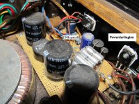
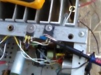
I just soldered a 150k over the 1M Resistor..., I´m really not shure but may be there`s more transparancy and less annoying highs with the Audyn caps. If I`m not wrong, it should no prob to reduce the 1M down to ~ 68k without any changes, the resulting highpass should be still under 20Hz. This would reduce the impedance at 1/15. Could be a good idea either to parallel the 33µ Cap with a Foil, cause I guess it`s more visible at a ground now. Maybe someone else likes to test if there is an improvement in sound and/or a less strong dependence in choosing caps. For the output cap I now ordered ELNA silmic II electros, should be the best choice (and cheaper...) next to BLACK GATES.
My ZCA, chaos again..., improvised red Audyn caps, the long silver ones are russian PIO, the darlingtons for the gyrator are on the main coolers. Getting tighter inside as I thought...
An externally hosted image should be here but it was not working when we last tested it.An externally hosted image should be here but it was not working when we last tested it.
Celeron this is the most aesthetically pleasing diy amp I've ever seen, nice work.
")
Did you try using chokes ( inductors ) before going for the gyrator circuit, Mark reckons that a CLC power supply is best, but I grew up believing that chokes are bad! Do you think the gyrator compares favorably?
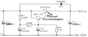
Taking another look at the circuit, the design parameters are quite wrong.
The 'mid point' output voltage should not be 12V. For maximum output into 8R it should be at 8 Volts. This would instantly quadruple the power output!
We'd get an earth shattering 4W rms. (with the original 15R resistor)
I've been thinking about this all afternoon and while yes in principle you could get 4w RMS with the 15 ohm resistor and the midpoint at 8 volts the MOSFET would have to switch hard on with only millivolts across the drain-source putting the transistor well outside the linear region THD would be huge surely. I'm not a qualified EE so feel free to correct me if I'm wrong.
In my recent delve into resistor loaded output stages i found an excellent alternative to resistors or light bulbs, hot water heater elements. Attached is a sheet with info on resistance and type. These can take some serious power without worry, but the size can sometimes be a bother.
Attachments
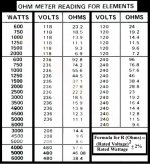
Jerluwoo, cool idea only thing is they can only dissipate their maximum rated power when submerged in a bath of water! If you applied full power without the water they would melt or even explode like a kettle with no water in it ( though in reality kettles have thermal cutouts to prevent this from happening ). Still I cannot conceive of an amplifier that would need to dissipate 1000 watts or more, so yeah the water heaters would make great resistors for <= 100 watts.
I work for a local retail\hobbist electronics store. We sell small spools of nichrome wire. Not sure but it may act like heater elements and may not need extra cooling.In my recent delve into resistor loaded output stages i found an excellent alternative to resistors or light bulbs, hot water heater elements. Attached is a sheet with info on resistance and type. These can take some serious power without worry, but the size can sometimes be a bother.
I still like the resistor idea. And still like choked PSs. Hugh Dean of Aksa amps here in Australia agreed with me that choked PSs always sound better than non-choked even in SS amps. Problem in SS amps amps is getting chokes which will handle a lot of current.
Member
Joined 2009
Paid Member
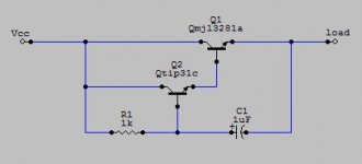
It's possible to emulate a choke easily. Adjusting the value of C1 to vary different size chokes.
I thought the -ve end of the cap went to ground or is that only for capacitance multipliers?
Is it called a gyrator by any chance?
I thought the -ve end of the cap went to ground or is that only for capacitance multipliers?
Is it called a gyrator by any chance?
A capacitance multiplier is entirely different. Some may call it a gyrator but it is considered an electronic choke. What the load see's mimics an inductor in that it has rising impedance with rising frequency which is controlled by the ratio of C1's impedance in relation to the value of R1.
Thanks Jerluwoo
Speaking of that, last night I read Nelson Pass' article on -ve feedback and how it introduces higher order harmonics that are uglier to listen to. It was like realizing that everything I was brought up to believe was a lie.
And of course
Speaking of that, last night I read Nelson Pass' article on -ve feedback and how it introduces higher order harmonics that are uglier to listen to. It was like realizing that everything I was brought up to believe was a lie.
Last edited:
A capacitance multiplier is entirely different. Some may call it a gyrator but it is considered an electronic choke. What the load see's mimics an inductor in that it has rising impedance with rising frequency which is controlled by the ratio of C1's impedance in relation to the value of R1.
Is there a formula for calculating the equivalent inductance that the circuit emulates?
Generally GNFB is the devil. A small amount of local NFB is good.Thanks Jerluwoo
Speaking of that, last night I read Nelson Pass' article on -ve feedback and how it introduces higher order harmonics that are uglier to listen to. It was like realizing that everything I was brought up to believe was a lie.
Guess what all the SS amps of the 60s, 70s, 80s and possibly more have in truckloads?
Interesting thread.
Being a ZCA owner and having used the same concept with Sony and Tokin VFETs, I know it can sound very good, with a sense of organicity and punch, with efficient speakers. Obviously, VFETs, being the superior devices compared with the 1058, make better amps. But, can the 1058 sound better?
Now I am on "cascode fever" so I found the time and I did the mod. It worked. One channel only for now and 16 Ohm test speakers so I cannot comment on sound.
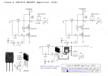
The Cascoded ZCA or maybe nZCA (nearly Zero Component Amp)
The one I did is the mod on the right, with BJT. Feel free to send your remarks and advices.
The idea is to gain experience to upgrade the VFET amps also...
Thanks Mark!
Being a ZCA owner and having used the same concept with Sony and Tokin VFETs, I know it can sound very good, with a sense of organicity and punch, with efficient speakers. Obviously, VFETs, being the superior devices compared with the 1058, make better amps. But, can the 1058 sound better?
Now I am on "cascode fever" so I found the time and I did the mod. It worked. One channel only for now and 16 Ohm test speakers so I cannot comment on sound.
The Cascoded ZCA or maybe nZCA (nearly Zero Component Amp)
The one I did is the mod on the right, with BJT. Feel free to send your remarks and advices.
The idea is to gain experience to upgrade the VFET amps also...
Thanks Mark!
Attachments
- Status
- This old topic is closed. If you want to reopen this topic, contact a moderator using the "Report Post" button.
- Home
- Amplifiers
- Solid State
- 5W Single Ended Class A Power Amp From Mark Houston