
And where was that, Danspy?
He's just mis-posted. The real question is, where's Line Up?

Wow this thread just woke up again - long time, no see.
I had been thinking of posting an update here as some people have been asking how the DC feedback & servo, choke regulation version of this amp has progressed.
Many years ago I read these web pages from Peufeu
Memory Distortion Philosophies
Thought it was very interesting but thought there was probably a lot more going on besides thermal distortion and because at the time I was labouring under ( what I now regard as ) a misconception that simplest is best, I never got around to trying any of these mods.
However, since then a couple of people here have commented on how much a strategically placed compound feedback pair or a cascoded CFP can transform the sound an amp. Most recently this advice came from Sonnya who posted about a year ago with regard to his nice TSSA design.
So I decided to try a CFP cascoded with a Jfet as the i/p transistor of my DC linked fetzilla. This means I can no longer call it a fetzilla ! and technically it no longer falls within the remit of this thread. Never-the-less I though I would post an update here as it may be of interest to all the fetzilla enthusiasts here.
There is one technical problem with adding this cascoded CFP - it introduces a 0.63V offset compared with the Jfet and this needs to be addressed. However my amps already had a Jfet follower driver stage so I changed to a higher IDSS Jfet here to give me a 0.63V offset feeding into the new compound i/p device - the servo took care of any minor anomalies.
I don't want to appear too over enthusiastic but in the context of this design, this is a very significant modification. Here are the main subjective changes:
The amps now sounds like it has more effortless power particularly in the bass which now sounds much deeper & fuller. The effect of this when listening to music is that instruments like saxophones sound fatter and more rounded - more like real instruments.
The other main area of improvement is low level detail which improved dramatically - and this is the good kind of unexagerated detail that just makes everything sound natural & realistic.
Sound staging is also improved.
From my limited theoretical understanding I think this cascoded compound FB pair comes close to being an ideal transistor and I am begining to think that the reason many transistor amps with global FB do not sound as natural as amps without, may be because the devices used to mastermind the operation of the feedback most often are not ideal enough.
So all in all I think this is a very significant mod.
If anyone would like to pursue this we can decide whether to start a new thread.
Last edited:
I see two major distortion mechanisms that would be eliminated by this.
A: The rectified load signals from the rails are no longer leaking into the output through Early effect on the input transistor.
B: A 2nd harmonic caused by Miller compensation currents which rises with frequency will be eliminated.
C: Both of these can be worsened by the high source impedance from a volume pot. If this is the case, it would be interesting to see if the sound improves if a buffer is used after the pot.
I don't know which of these effects is stronger (they are certainly not equivalent sonically), and I don't know where they stand in relation to distortions produced by the rest of the circuit.
Hi KT,
Adding a buffer to give low impedance drive to the input is a definite plus for several reasons including stability. I had the idea that the drive impedance should be significantly lower than the gain resistor in the feedback path.
Also adding a buffer enables the use an input HF filter with lowering input drive impedance.
Subjectively all these factors amounted to a definite improvement when I added the buffer.
Last edited:
I am happy that people see the worthy of cascodes/ cascades etc, because of the uge headroom and little memory effect, however stability has to be care for, use of big emittor resistors wil help, the sound of a casode is always very nice, I use them in the hybrid.
regards
kees
regards
kees
Last edited:
Amplifiers with degenerated BJT input stages (and the Fetzilla counts) will be less sensitive to source impedance than amps without, such as a plain LTP input stage. That is to say, the source impedance necessary to double distortion at the output will be larger for amps with degenerated BJT input stages (and much larger for FET input stages).
Often I find myself wondering why most BJT amps don't already have a buffer built into the input, if it's that much of an improvement. A single-transistor buffer can be sufficient and have pretty much no distortion to speak of.
Often I find myself wondering why most BJT amps don't already have a buffer built into the input, if it's that much of an improvement. A single-transistor buffer can be sufficient and have pretty much no distortion to speak of.
Amplifiers with degenerated BJT input stages (and the Fetzilla counts) will be less sensitive to source impedance than amps without, such as a plain LTP input stage. That is to say, the source impedance necessary to double distortion at the output will be larger for amps with degenerated BJT input stages (and much larger for FET input stages).
Often I find myself wondering why most BJT amps don't already have a buffer built into the input, if it's that much of an improvement. A single-transistor buffer can be sufficient and have pretty much no distortion to speak of.
The buffers brought benefits even with a Jfet i/p
I don't see a down side with i/p buffers on any amp.
Mike,
I take your points very seriously.......
Thank you for your posts, Kean too, much appreciated!
Hugh
This is very interesting. Could you please give me a sliver of the input stage in schemat so I can be absolutely sure what you are meaning?decided to try a CFP cascoded with a Jfet as the i/p transistor of my DC linked fetzilla
I take your points very seriously.......
Thank you for your posts, Kean too, much appreciated!
Hugh
Hi Hugh,
I think out of all the threads I joined in this forum, this one was the one that seemed most in the spirit of friendly, open minded co-operation and positive lively debate. Many thanks for all your input. Happy to be chatting here again.
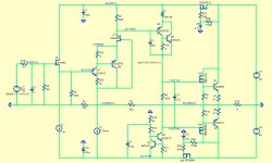
Here is the somewhat simplified schematic that shows more or less what I'm listening to at present. Please ignore the actual parts - I switched to LT spice a while back and am finding it almost impossible to import parts - perhaps coz I'm running W7 on a MacBook - so I just use whatever parts are in the box to get an idea of what is going on. My output devices are still buffered lateral mosfets.
I2 is in fact a servo controlled variable CCS.
I think out of all the threads I joined in this forum, this one was the one that seemed most in the spirit of friendly, open minded co-operation and positive lively debate. Many thanks for all your input. Happy to be chatting here again.
Here is the somewhat simplified schematic that shows more or less what I'm listening to at present. Please ignore the actual parts - I switched to LT spice a while back and am finding it almost impossible to import parts - perhaps coz I'm running W7 on a MacBook - so I just use whatever parts are in the box to get an idea of what is going on. My output devices are still buffered lateral mosfets.
I2 is in fact a servo controlled variable CCS.
Attachments
If every Source had a buffered output, then we would not need this conversation.
Hi Andrew,
This may be true unless you have a preference for an input low pass filter without loosing low impedance drive - which was the main original motivation for me to add a buffer.
if you have a low pass and I always recommend that, then using a 1k +1nF as the filter works.
But D.Self and others tell us that 1k is far too high and that 100r +10nF is likely to be better.
Now the input sees the source as 100r||10nF.
that is pretty low impedance as a source impedance goes.
And for an especially low Rs, then 10r and 100nF goes even lower, provided the buffer at the other end can drive 100nF isolated with just 10r.
Nice mikelm!Hi Hugh,
I think out of all the threads I joined in this forum, this one was the one that seemed most in the spirit of friendly, open minded co-operation and positive lively debate. Many thanks for all your input. Happy to be chatting here again.
Here is the somewhat simplified schematic that shows more or less what I'm listening to at present. Please ignore the actual parts - I switched to LT spice a while back and am finding it almost impossible to import parts - perhaps coz I'm running W7 on a MacBook - so I just use whatever parts are in the box to get an idea of what is going on. My output devices are still buffered lateral mosfets.
I2 is in fact a servo controlled variable CCS.
When I started this thread I had no idea it would become popular.
And if it wasn't for Hugh AKSA it wouldn't have lived long.
His contributions are worth gold
")
if you have a low pass and I always recommend that, then using a 1k +1nF as the filter works.
But D.Self and others tell us that 1k is far too high and that 100r +10nF is likely to be better.
Now the input sees the source as 100r||10nF.
that is pretty low impedance as a source impedance goes.
And for an especially low Rs, then 10r and 100nF goes even lower, provided the buffer at the other end can drive 100nF isolated with just 10r.
I take your point but personally I prefer to offer an easier load to the previous stage.
edit: 1K & 1n is not too high an impedance for a Jfet follower I think
Last edited:
I don't have the resources nor the knowledge to confirm that.I take your point but personally I prefer to offer an easier load to the previous stage.
edit: 1K & 1n is not too high an impedance for a Jfet follower I think
But I habitually use 1k + 680pF as my low pass and it seems to work for all audio signal passing and give a lowish source resistance to the input stage.
The 1nF instead of 680pF would be even lower, so recently I have tried a few low pass @ 680r +1nF and this too works, but I can't admit to hearing any difference.
Maybe I should go down to 300r + 2n2F, for an even lower Rs as far as the input stage is concerned. No data to back that up.
Does anyone have data to show that Self's recommended 100r is better than 300r, or 1k, as the input resistor of the low pass?
Nice mikelm!
When I started this thread I had no idea it would become popular.
And if it wasn't for Hugh AKSA it wouldn't have lived long.
His contributions are worth gold
Hi Lineup,
good to see you and thx for starting this great thread.
Interestingly, your original idea was inspired by a good measured performance in spice from a simple circuit.
However, I am not aware that this new mod brings any obvious change in measured performance but subjectively the sound has changed significantly.
It now has a full bodied, warm sound that many solid state designs lack when compared to a good valve design.
When I listen to real acoustic instruments close up ( thx to all those buskers ) that warm, full bodied sound is what I hear.
Thank you Mike, Lineup,
You are great guys, and wonderful community people. Generally, the truly objectionable behaviour comes from the very clever people who know more than everyone else; not with you guys....... a credit to your restraint and temperament.
Now, Mike your amp is HUGELY different. Let me count the ways:
1. jfet source follower with CCS buffer driving not just a singleton, but a CFP master running at only 650uA! To me, I must admit it's like wearing three pairs of socks.......
2. A CFP singleton input stage with constant power cascade. (Q4, Q6 and J3). I did some sims on this and replacing the singleton with a CFP singleton, albeit without the cascode, delivered NO improvement on distortion, I found it was around the same THD figure, no more, and normally a jfet is cascaded by a bipolar to get around the Vds issues. This is reversed; it seems topsy turvy to me.
3. I strongly support the unchanged buffered Q2 VAS though I'm not quite sure why you put in D1. A great idea from Graham Maynard about 15 years back, and very clever and we know works very well. Linear amplification with very low Zout.
4. No bootstrap, Mike? Tsk tsk....... I love 'em, they improve the human voice and the ratio of the resistors can profile the harmonics too. Very helpful, and very reliable.
5. Complementary mosfet master/bipolar slave double emitter OPS? WOW!! It is so reversed over the usual approach that I would expect it would sound very difficult.
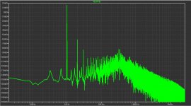
Finally, this is not to pooh pooh your circuit. You say it sounds wonderful, BUT, I count off 14 semiconductors, including series cap multipliers, and in fact there is no inclusion of thermal bias control. The profile in post #2357 indicates falling H2, H3 and H4, but rising H5 and beyond..... not the Hiraga profile I seek and which can be manipulated nicely in the FetZilla...... HOWEVER, subjective rule, OK? If this sounds better than the bog standard Fet, then we need to take note. BUT, I don't like the semi count, too many bits!
Thanks Mike..... You have taken a Crewe V8 and turned it into the new 4 litre DOHC twin turbo.....
Cheers,
Hugh
You are great guys, and wonderful community people. Generally, the truly objectionable behaviour comes from the very clever people who know more than everyone else; not with you guys....... a credit to your restraint and temperament.
Now, Mike your amp is HUGELY different. Let me count the ways:
1. jfet source follower with CCS buffer driving not just a singleton, but a CFP master running at only 650uA! To me, I must admit it's like wearing three pairs of socks.......
2. A CFP singleton input stage with constant power cascade. (Q4, Q6 and J3). I did some sims on this and replacing the singleton with a CFP singleton, albeit without the cascode, delivered NO improvement on distortion, I found it was around the same THD figure, no more, and normally a jfet is cascaded by a bipolar to get around the Vds issues. This is reversed; it seems topsy turvy to me.
3. I strongly support the unchanged buffered Q2 VAS though I'm not quite sure why you put in D1. A great idea from Graham Maynard about 15 years back, and very clever and we know works very well. Linear amplification with very low Zout.
4. No bootstrap, Mike? Tsk tsk....... I love 'em, they improve the human voice and the ratio of the resistors can profile the harmonics too. Very helpful, and very reliable.
5. Complementary mosfet master/bipolar slave double emitter OPS? WOW!! It is so reversed over the usual approach that I would expect it would sound very difficult.
Finally, this is not to pooh pooh your circuit. You say it sounds wonderful, BUT, I count off 14 semiconductors, including series cap multipliers, and in fact there is no inclusion of thermal bias control. The profile in post #2357 indicates falling H2, H3 and H4, but rising H5 and beyond..... not the Hiraga profile I seek and which can be manipulated nicely in the FetZilla...... HOWEVER, subjective rule, OK? If this sounds better than the bog standard Fet, then we need to take note. BUT, I don't like the semi count, too many bits!
Thanks Mike..... You have taken a Crewe V8 and turned it into the new 4 litre DOHC twin turbo.....
Cheers,
Hugh
Last edited:
- Status
- This old topic is closed. If you want to reopen this topic, contact a moderator using the "Report Post" button.
- Home
- Amplifiers
- Solid State
- JFET input, MOSFET VAS, LATERAL output = Perfect!!