mikelmI never expected to see a feedback amp with a Push Pull o/p that can operate with normal loads without any compensation - truly a step forward.
p.s. does anyone know where I can buy 2sk170's or Lsk170's in europe ? the ones I have will probably only arrive in about six weeks - can't wait that long
Mouser is a good seller of 2SK170BL.
Has got salesfuntion for UK.
Has got lower price than Farnell to order.
2sk170
This is the one to buy:
2SK170BLF Toshiba JFET
MiiBthe BF862 part in my circuit might be even better....it's easy to get...and has less noise and twice the gain...
It is well worth to investigate.
I know BF862 is a great JFET.
I am adding the SPICE Model of BF862 to my library.
Last edited:
BUILD the amplifier WITHOUT capacitance compensation
For the builders it is good with an amplifier that is stable
without compensation. There are other benefits with lower OLG.
I am happy to see
swordfishy has built an amplifier without compensation cap.
I will publish a diagram from swordfishy's latest.
With a bias of the JFET with CCS from negative rail.
Here is swordfishy's great amplifier again:
I tried a Hawksford Cascode and at 1 Watt 1 kHz it even was worse data.It mainly works at high signal levels... when you push the amplifier...the cascode prevents the higher harmonics from building up...and aids so to speak the amplifier to maintain it's character a different signal levels.
So you say it is at higher power the benefit comes.
On the other hand, cascoding is not necessary for good result i this amplifier.
By complicating we can make people think amplifier looks complicated.
And they buil something more simple instead.
Some other amp. Like Hiraga orr JLH.
MY saying is NO to ANY cascode of Fetzilla.
Regards
Lineup,
I actually tried removing the Feedback Cap yesterday and had some pretty bad DC offset issues. Not sure if this will apply with the CCS version, but it was pretty terrible with the front bias version.
I don't know what you mean by Feedback Cap????
Bad DC Offset can sometimes indicate an OSCILLATION going on.
I think regarding DC linking ( or for that matter any other variation ) it is important to make sure that the design is modified suitably so that it is re-optimized with the new element added.
With DC linking the front bias circuit is not necessary and is probably better to remove it.
I am not clear from swordfishy's remarks about DC linking whether the DC offset was terrible or the sound was terrible but I do feel fairly confidant that if it is implemented carefully and thoughtfully that it will sound better.
The main point I am making here is that it is not really valid to judge the inclusion of a particular feature unless the design has been thoughtfully adjusted to accommodate it.
I have been reading about LSK170 from LT. It seems like a better device. Can anyone think why using this would not be a good idea ?
mike
Mike,
I would caution on removal of the 1000uF feedback shunt cap.
Yes, this gives DC linking, no question, but there is a problem.
The offset voltage of the output stage is divided by the gain, giving much reduced control over offset correction. The consequence of this is very loose offset control, at times quite high values, particularly as the Vgs of the IRF9610 VAS varies considerably with temperature, affecting the voltage drop across the feedback shunt resistor.
Hugh
Mike,
I would caution on removal of the 1000uF feedback shunt cap.
Yes, this gives DC linking, no question, but there is a problem.
Hugh
I appreciate you concern Hugh but,
Every amp I built and happily used for the last 10 years has been DC linked including a version of the JLH simple class A .
Sure, there was some DC offset, but with some thought & effort it can be managed and reduced to acceptable levels as TimA has demonstrated & documented. For me the rewards are very well worth the effort needed to achieve this.
Anyway, no worries, I accept that some seem to have an aversion to taking this route but for me it is fundamental. I'm in this pursuit to aim for a sound that is natural & wonderful, and for me, this cannot be achieved with caps in the mix - perhaps a Teflon film cap would be OK and I confess that I didn't try biasing then with DC before, but electrolytics are just too much.
Susan Parker rejoices that she has no caps in her transformer linked Zero Feedback Power Amplifier but for me transformers & caps are all in exactly the same category.
Perhaps my o/p fuses won't blow and I will blow up my speakers and you can all have a laugh, but I don't mind I would buy another set still stay with DC linking.
Sorry to go on like this you don't seem to realise that I really don't like the sound of capacitors.
But I will build swordfishy's amp as a reference and am happy to hear from anyone about the best sounding 1000uF cap to use but I will be amazed if I prefer the sound because I've been here so many times before.
kind regards despite my ranting
mike
")
Last edited:
Near perfection....finely tuned
Hi All,
Well I just tried a few more things and now we're really getting somewhere.
First, I increased the input drain resistor to 1k to bring the current down to 4.5mA. All good, no adverse sonic affects.
Second, I added the filter cap to the input bias as lineup suggested. Not really any sonice affect, but clearly good practice.
Third, I added a grounding resistor to the input.
Fourth, I tackled the capacitive load overshoot and ringing square wave issue. I tried three things:
1) I wired a 4.7nF cap from the VAS to the output as was suggested here by Sonnya. This caused the amp to oscillate so I quickly removed it and aborted the idea.
2) I tried a 150pF miller cap. Made no difference.
3) I was so keen to try Hugh's idea of a cap from the VAS to the JFET source that I improvised and used 3x 150pF polypropylene in series for 50pF. Perfect. Now no capacitive load under 100nF makes any change to the 20kHz square wave that is worthy of mention. A 1uF cap will still make it do some funky things, but better than before.
It may be the placebo effect, but I would suggest that it sounds better too...
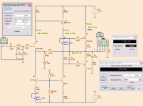
So ladies and gents, here is the current circuit. It is very good indeed. I think a change of VAS fet may make it even better!
Hi All,
Well I just tried a few more things and now we're really getting somewhere.
First, I increased the input drain resistor to 1k to bring the current down to 4.5mA. All good, no adverse sonic affects.
Second, I added the filter cap to the input bias as lineup suggested. Not really any sonice affect, but clearly good practice.
Third, I added a grounding resistor to the input.
Fourth, I tackled the capacitive load overshoot and ringing square wave issue. I tried three things:
1) I wired a 4.7nF cap from the VAS to the output as was suggested here by Sonnya. This caused the amp to oscillate so I quickly removed it and aborted the idea.
2) I tried a 150pF miller cap. Made no difference.
3) I was so keen to try Hugh's idea of a cap from the VAS to the JFET source that I improvised and used 3x 150pF polypropylene in series for 50pF. Perfect. Now no capacitive load under 100nF makes any change to the 20kHz square wave that is worthy of mention. A 1uF cap will still make it do some funky things, but better than before.
It may be the placebo effect, but I would suggest that it sounds better too...
So ladies and gents, here is the current circuit. It is very good indeed. I think a change of VAS fet may make it even better!
Attachments
Last edited:
Mike,
It's a pleasure to hear your kind rantings despite my best regards...... everyone has a point of view, and it's an intolerant fellow who can't handle that!
SWF,
I'm really pleased phase lead has had the desired effect. You'll be pleased to know John Linsley Hood loved this method of stabilising amps, and always suggested that it was best on its own, without a Miller cap if you could avoid it. Congratulations, you are certainly in good company now!!
Hugh
Last edited:
JLH always advised a bit more stabilisation rather than a bit less precisely because it made it sound a bit better
he wrote few books
http://www.amazon.co.uk/John-Linsley-Hood/e/B001HD0TGE
check this out
he wrote few books
http://www.amazon.co.uk/John-Linsley-Hood/e/B001HD0TGE
check this out
Last edited:
Hugh, mikelm, all,
With the 50pf of compensation outlined in post 531, the square wave is now clean up to 100nf of capacitive load. I would expect that further compensation would improve things further. What are the pros and cons of adding more capacitance here?
Thanks for your input.
Btw, mikelm that link did not work, but I'll go search for jlh at amazon.
Thanks Mikelm, I'm going to order what I can find of those.
Here is the current 20 volt peak to peak, 20kHz square wave with 7.27R and 100nF... Anything below 100nF looks much the same. 1uF is pretty messy, but a vast improvement on yesterday. Need I pursue this issue further or are these results good enough?
I have dropped the VAS current to 15mA as the devices were getting quite warm with no heatsink.
Edit: I posted the wrong photo. This is shot is actually with 75pf of compensation, but 50pf looks pretty much identical
Attachments
Last edited:
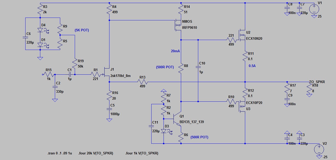
Hello swordfishy and mikelm
I have made an official version of Fetzilla
Eventhough people are free to build how they like
this is the one version I recommend people to build.
It is based on swordfishy's published amp, with super-good sound.
What is remarkable is that his amp is stable without compensation cap.
This is because of IRF9610 lower gain
but also emitter degeneration of VAS IRF9610 with one 49.9 Ohm capacitor.
This version below should be equally stable, sound good
and not give any headache with oscillation.
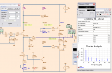
Fourier analyse at 1 kHz shows nice spectrum
with H2 and H3 sticking out. This is how we want it.
I be back with further tests later.
swordfishy
Could you setup this official version
should I be happy. Do it only if you want to.
I have made an official version of Fetzilla
Eventhough people are free to build how they like
this is the one version I recommend people to build.
It is based on swordfishy's published amp, with super-good sound.
What is remarkable is that his amp is stable without compensation cap.
This is because of IRF9610 lower gain
but also emitter degeneration of VAS IRF9610 with one 49.9 Ohm capacitor.
This version below should be equally stable, sound good
and not give any headache with oscillation.
Fourier analyse at 1 kHz shows nice spectrum
with H2 and H3 sticking out. This is how we want it.
I be back with further tests later.
swordfishy
Could you setup this official version
should I be happy. Do it only if you want to.
Attachments
Last edited:
I would be interested to find out if this version with the CCS to the neg rail sounds as good as the the version swordfishy has built.
Personally I was so happy to see the critical FB point not connected to a power rail - thus with no possibility of power rail noise polluting the delicate signal . . .
. . . but if it sound the same or better when we do have a CCS to the neg rail I can implement exactly the same anti DC offset measures as Tim Andrews did which would be just great.
mike
hello mikelm
I'd be happy if you tested my circuit in real life.
swordfishy tested DC-linked version, with no big cap.
he was not happy DC-offset problems, like Hugh suspected.
I think you need not test the DC-linked version without cap.
It is simply not good and safe.
But the official version I posted now should not cause any problems.
I think it might sound good, too.
I suspect the VAS with IRF9610 is working wonders.
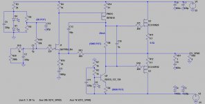
Only thing I forgot is one 2.2uF cap across the Gates of output.
Like in diagram below:
I'd be happy if you tested my circuit in real life.
swordfishy tested DC-linked version, with no big cap.
he was not happy DC-offset problems, like Hugh suspected.
I think you need not test the DC-linked version without cap.
It is simply not good and safe.
But the official version I posted now should not cause any problems.
I think it might sound good, too.
I suspect the VAS with IRF9610 is working wonders.
Only thing I forgot is one 2.2uF cap across the Gates of output.
Like in diagram below:
Attachments
- Status
- This old topic is closed. If you want to reopen this topic, contact a moderator using the "Report Post" button.
- Home
- Amplifiers
- Solid State
- JFET input, MOSFET VAS, LATERAL output = Perfect!!