Damping Factor
Hi All,
I wanted to measure the damping factor of my fetzilla as Hugh and I were discussing the possibility that the warm and extended bass of the amplifier is due to a low damping factor having poor control over the woofer.
Well, assuming I have done it correctly I was pleasantly surprised!
First let me remind you that my gain is 26dB, I think, my feedback network is 51.1R/1k - tell me if I have done this incorrectly.
Anyway, I ran a 1kHz square wave through the amplifier with no load attached and got a peak voltage of 30.2V (output choke was attached).
I then attached a 7.37R load resistor (choke still attached), and measured a peak square wave voltage of 29.6V across the resistor. This, I think, translates to 4.02A of current and a 0.6V voltage drop. This in turn implies an output impedance of 0.6/4.02 = 0.15R, or a damping factor of 8/0.15 = about 53!
Not at all bad huh?! Especially when one considers the very low transconductance of the devices I use, my VAS device has a transconductance of only 50mS!
Now, this is all assuming I have done this correctly, which I am by no means sure about. And there will be slight errors, but if my methodology is correct I would say that the damping factor could not be under 40, and that is being ultra conservative!
This amplifier never ceases to surprise. While it is not anything crazy like some of the "blameless" amplifiers, a DF of over 50 is pretty respectable huh?
Greg,
I get a Zout of 0.146R according to your figures (1 - 29.6/30.2) x 7.37.
This tallies pretty well.
I would say the choke would take up most of this in its DCR, and that in fact the Zout of the amp alone is probably quite a bit less, maybe only 0.05R. The intrinsic Zout of each output (only one effectively operates at once into the speaker) is recip 0.7S plus the source resistor - around 1.5R. This is approximately reduced by the loop gain factor.
Cheers,
Hugh
50ish including the DCR of the output inductor and all the other connections in the test setup is better than adequate. I would put it into the good class.
If, as Aksa is suggesting, the amp output impedance is ~50milliohms (0r05), that value is swamped by all the cables and connections from the amp output to the driver terminals (driver terminals!!! not speaker terminals). Resistances total in the flow and return circuit can easily reach 200milli-ohms.
If, as Aksa is suggesting, the amp output impedance is ~50milliohms (0r05), that value is swamped by all the cables and connections from the amp output to the driver terminals (driver terminals!!! not speaker terminals). Resistances total in the flow and return circuit can easily reach 200milli-ohms.
This was not a question on discharging subjective impressions.. those are truly the most significant in any evaluation...But adding a coil off just 0.1 mH starts rolling off the amp off at app 20KHz.. and while it may sound better in a specific system It hardly improves the amplifier.. The right fix would be to fix the speaker and then evaluate the amplifier....
Last edited:
Homemodder,
This implies I am endeavouring to deceive people.
Nothing could be further from the truth.
It is MY experience over years in this game with all types of caps.
I offer it here without obfuscation or hype.
Have I been rude to you? If so, perhaps your comment is justified, though not in a public forum. Otherwise, I would like a retraction.
Hugh
Hi Hugh
No you havent been rude to me and I think you took what I said the wrong way although I do think you have been misled too.
Later you made this claim :
Actually, I find the figure of merit for a cap is the dielectric absorption, which I don't believe is given in SWF's chart?
Do you know how wrong this is ??
Silver Mica has DA 3 to 10 times worse than the other film caps, it would rate the micas as one of the worst caps to use in audio. It is exactly this high DA that makes them inferior for use as comp cap compared to polistyrene, polyprops and teflon caps. If you happen accross Bob Pease s paper on this matter you will find actual experiments and measurments done by himself relating to DA and problems that might present themselves. His measurements show Teflon followed by polyprops, polistyrene and COG are far superior to Mica. These other film caps also display other caracteristics like temp coeff as good or better than mica. This is fact.
Your claim that silver mica is superior to polistyrene is unfounded, polistyrene has lower DF and lower DA. (Now Im not 100 % sure on the DF but in any case it will be a close call)
Hugh there are a lot of members here that do not know anything much about electronics and statements like yours is misleading them. Mica is in no case superior not even objectively according to me, my vote goes for teflons although I use high voltage polistyrene for vas comp. Mica works fine for vas comp but when using it in pole zero compensation schemes I have found some problems and this I can only point to the high DA of mica.
Mica works fine for vas comp
I think that was Hugh s whole point , as miller compensation caps, as it
doesnt seems to me that he mentionned another purpose...
")
I think that was Hugh s whole point , as miller compensation caps, as it
doesnt seems to me that he mentionned another purpose...
No the point was "PS is good, but silver mica is better still - but expensive" , this is incorrect.
And so is this :
"Actually, I find the figure of merit for a cap is the dielectric absorption, which I don't believe is given in SWF's chart?"
Last edited:
http://www.diyaudio.com/forums/soli...ility-techniques-zobel-et-al.html#post1653831
http://www.diyaudio.com/forums/chip...-mobile-phone-blips-speakers.html#post1153679
I have a paper copy of Cherry somewhere.
It looks like I need to dig it out, photograph it and post here.
http://www.diyaudio.com/forums/chip...-mobile-phone-blips-speakers.html#post1153679
I have a paper copy of Cherry somewhere.
It looks like I need to dig it out, photograph it and post here.
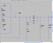
output coil
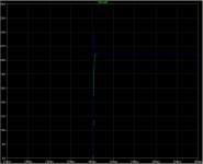
I took a simulator example that Paul had sent me to look at quelling the ringing when driving the 100nf load. The first example is what I will call the baseline example. The sim steps through a 1p load and then a 100nf load. The green trace is the 1pf and the blue is the 100nf.
I took a simulator example that Paul had sent me to look at quelling the ringing when driving the 100nf load. The first example is what I will call the baseline example. The sim steps through a 1p load and then a 100nf load. The green trace is the 1pf and the blue is the 100nf.
Attachments
output coil part two

 In this second series, I added a cap and resistor after the coil as well. I fiddled with the values a bit compared to Andrew's spread sheet, and got the following plots. Adding the cap and resistor after the coil clearly helped along with reducing the resistor value parallel to the coil. Obviously your results will vary...
p.s. I think I changed the cap load values to 100nf and 470nf for this run, so, the 100nf show no ringing and the 470nf has a bit of ringing.
In this second series, I added a cap and resistor after the coil as well. I fiddled with the values a bit compared to Andrew's spread sheet, and got the following plots. Adding the cap and resistor after the coil clearly helped along with reducing the resistor value parallel to the coil. Obviously your results will vary... p.s. I think I changed the cap load values to 100nf and 470nf for this run, so, the 100nf show no ringing and the 470nf has a bit of ringing.
Last edited:
Well, Homemodder, I'm apparently guilty of ignorance, but you are guilty of unsociable belligerence.
I'd say we were square, wouldn't you?
Silver mica is ideal for miller compensation, my point. As for the point on DA v. DF, it's is semantic drivel, not worth answering.
I really would like to meet you. I'm sure there'd be sparks......
I'd say we were square, wouldn't you?
Silver mica is ideal for miller compensation, my point. As for the point on DA v. DF, it's is semantic drivel, not worth answering.
I really would like to meet you. I'm sure there'd be sparks......
ZVP2110A
Hi all,
Today I tried the zvp2110a in my vas. I dropped it straight into my existing circuit with no compensation. Did a stability test, all ok, though overshoot is significantly greater than before so perhaps getting closer to instability. Anyway, I added my output choke which completely removed it.
Sound is excellent. Mids and especially treble are cleaner and and the amp seems to have a better transient response. Some of the warm extended bass is gone, but only a little bit, and it has been replaced by greater control.
This is currently my favourite vas device.
This weekend I try the zvp4424a, though I suspect it will require compensation.
I might add that the zvp2110a is the to92 version of the device for which Hugh has made his boards, the zvp2110g.
It will be interesting to find if more some gain that requires just a little compensation - so that overshoot is matched - sounds the same as less gain with no compensation.
If a miller cap improves the sound by adding some good quality capacitance to the VAS device then perhaps to add the raw excitement back in we just increase the gain to add a little bit of instability / ringing and then clean it up again with an o/p choke !
Does that sound like a good plan ?
If a miller cap improves the sound by adding some good quality capacitance to the VAS device then perhaps to add the raw excitement back in we just increase the gain to add a little bit of instability / ringing and then clean it up again with an o/p choke !
Does that sound like a good plan ?
- Status
- This old topic is closed. If you want to reopen this topic, contact a moderator using the "Report Post" button.
- Home
- Amplifiers
- Solid State
- JFET input, MOSFET VAS, LATERAL output = Perfect!!